This is a placeholder topic for “8 Channel Solid State Relay Module” comments.
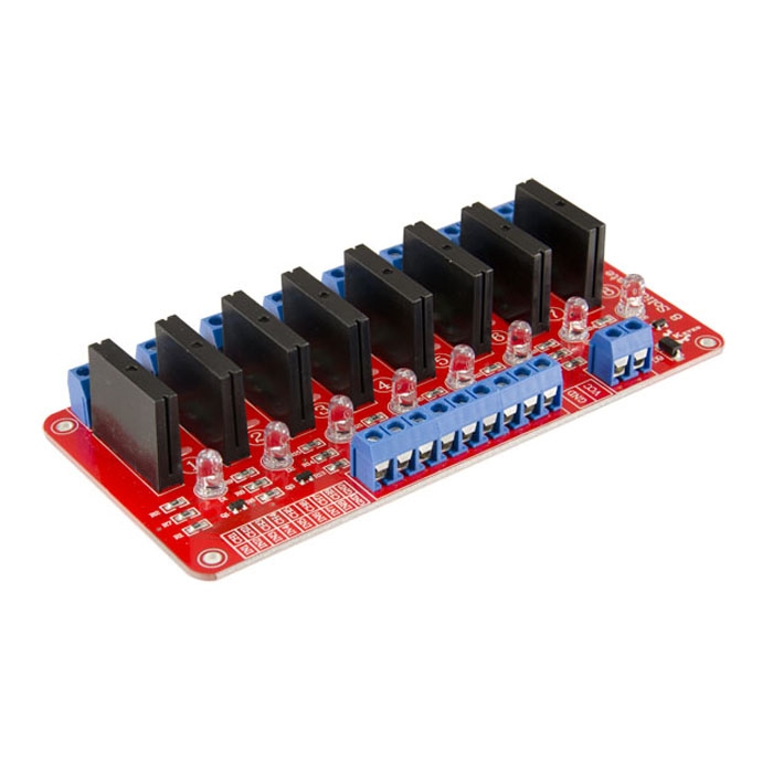
This breakout module gives you access to a 8 channel solid state relay that can be switched with 3-5VDC
Read more
This is a placeholder topic for “8 Channel Solid State Relay Module” comments.
This breakout module gives you access to a 8 channel solid state relay that can be switched with 3-5VDC
Can you please Datasheet for your 8-channel relay board SKU CE05343 - I cant see any on the product information.
Thankyou.
Hey Scott,
I’ll put that in our to-do list and we’ll get onto that for you when someone from the team is able to fix it. Have a great day!
Bryce
Core Electronics | Support
Any update on this? Is this certified in auatralia to connect mains into it? Thanks
Hi Daniel,
At this point in time there’s no legal certification that we supply to confirm its compatibility. That would need to be discussed with the OEM directly. Otherwise, I can confirm that the solid-state relays being used are OMRON G3MB-202P 30Y4E and that the team is working on finding some English references to their specifications. But there should be some information here if the link is still functional.
Bryce
Core Electronics | Support
Can anyone advise whether this relay would be suitable for 24VAC loads (watering system solenoids)?
I have 8 sprinkler zones that I’m looking to control with a RPi, and I’m hoping this module will be suitable. I’ve written the code, I’ve done the plumbing…now for the electronics. I’ve pretty much copied an example I found at https://www.instructables.com/id/Raspberry-Pi-Controlled-Irrigation-System/, leaving out a few of the extra LEDs.
Hi Andrew,
Unfortunately, this particular relay is not suitable as they’re rated to a required output of 100-240 V as listed on the datasheet below.
That being said, there’s another relay available that I’ve also added to this forum post that should be suitable for your particular project, please note that this is a mechanical relay, as oppose to solid state, so it will wear more quickly under frequent use.
If there’s anything else that I can do for you please let me know.
Bryce
Core Electronics | Support
Hi Bryce,
Thanks for your assistance, I haven’t touched electronics since high school, so this is a real learning experience. I had seen the g3mb-ssr-datasheet.pdf but thought the 100-240 V was a maximum. Looking at the both data sheets I can see lots of maximums listed, but which graph or figure did you look at to determine the minimum, i.e. that it’d be suitable for my project (especially in the G5LE datasheet)?
Regards,
Andrew
Hi Andrew,
The G3MB is a solid state relay, the control (input) side is rated for low voltage DC but the load (output) side is rated for 100V-240V AC. Quite simply, 100V is much higher than the 24V AC you need it to work with.
Omron have some good information on using SSRs here: https://omronfs.omron.com/en_US/ecb/products/pdf/precautions_ssr.pdf (See Load Power Supply, 3. Low AC Voltage Loads)
The G5LE is a mechanical relay, so these don’t tend to have minimum AC voltages. Note that the switching current graph for the G5LE goes all the way down to 0 volts.

For anyone else reading, but thinking about working on 240V AC: please keep in mind that it is illegal in Australia for an unlicensed person to perform work on mains wiring (and all mains electrical work must comply with AS/NZS 3000 - The Wiring Rules). Not following standards can be deadly for the next person to work on it (no one’s around forever), or yourself.
Regards,
Oliver
Support | Core Electronics
Hi,
Could You please advise me on what software controls and switches relays? Also what is max amps that relays can switch?
Hi Jason,
Welcome to the forum!  It’ll depend on the relay, usually, they’re either 5A or 10A but it should be listed on their spec sheets or on the relay itself, we can check for you if you’d like to link it here (if you can’t add links you can type the SKU from our page). As for the software to control the relay, you can use anything that you’d like on any microcontroller with the appropriate voltage output to drive them. Most projects run on Raspberry Pi or Arduino boards, but anything with GPIO in the right rating should do the trick. Make sure to let us know if you have any further questions. I’ve linked a tutorial below that you may be interested in regarding this topic. Have a Merry Christmas!
I used a 4 channel and 1 channel module; which uses the same OMRON relay. The supply is 24 VAC, the solenoid draws about 500mA and the relay switches it ON and OFF ok. If you have NO load it is hard to tell if the relay is working or not, it needs a load to operate.
In my opinion the relay will work with 24 VAC watering system solenoids, as long as the load is enough to switch the Triac.
Regards
Jim
Old post but needs clarification.
I’ve been using this board to switch 24vac irrigation solenoids for over 12 months at time of writing, controlled by a RPi Zero W using Opensprinkler. It works reliably without modification.
Hi All
This is an old post but Tim has revived it and I have just noticed James’ reply to Andrew.
This is quite true
This is not quite the case. The Triac will switch at the zero crossing of the AC signal with or without a load but without AC being supplied (as in DC or maybe nothing) the zero detection system will not allow switching. The reason you would still measure voltage with no load or a very light load when switched off is due to a built in snubber comprising a resistor and capacitor in series across the “contacts”. There is enough leakage here to measure volts with a DMM or even power very light loads (a few mA) with the relay OFF which could give the impression that the relay has not turned off.
Cheers Bob
@Robert93820 That would explain what I observed at very low current loads.
Cheers
JIm
Hi James
Yes it is a bit annoying but nothing can be done as this snubber circuit is built in.
This was a real problem with a project I was involved in quite a few years ago. The fix was to fit a 240VAC MAINS RATED capacitor from the load side of the relay to neutral. This killed off most of the leakage so the connected load actually switched off. This was at the expense of a bit of an increase in load but with plenty in hand was not an issue.
It is too far back to remember what value was used so if you have this problem it would be a case for experiment but it is important that it is MAINS RATED.
Cheers Bob
Do I need to have a snubber circuit for the 8 channel solid state relay to prevent against re-energizing of 24vAC solenoid vale
Hi Satheesh
says it all.
I think you will find your 24VAC solenoids are enough of a load to prevent them being energised via the snubber circuit. Should be all OK.
These have been used successfully (I assume) in the past to control 24VAC water solenoid valves.
Cheers Bob
do you have a esp32 board that can be used to control SSR relays ? I have tried using 16A AC relays and they have been sticking so wanting to try heavier duty SSR relays , also ideally after a board that any esp32 device can be swapped into if it dies ie) not built in / soldered to the board but can plug into the board
Hi Christopher
If you were a bit more specific you would have a better chance of getting a response
Is this relay 16A AC operated or 16A AC load. Is the "sticking a SSR or electromechanical type.
There are a couple of failings with SSR relays. Most switch at zero volts crossing so will only switch AC loads. DC never gets to zero volts so will not switch. You can get switch at any time devices but these are not common.
Another more obscure one is that most have a “snubber” circuit which is a capacitor and resistor in series across the “contacts”. This is effectively in series with the load when switched OFF. If your load device is light and only requires a few mA this snubber will allow enough leakage to quite often keep the load ON. Thus giving the impression that the relay has not released. this could well be your “sticking”. It is possible that some electromechanical relays also have such a circuit either built in or externally fitted which would do the same.
Cheers Bob
And you can get our latest projects and tips straight away by following us on:
![]()
![]()
![]()
![]()
