Adafruit Trinket - Mini Microcontroller - 5V Logic (ADA1501)

This is a placeholder topic for “Adafruit Trinket - Mini Microcontroller - 5V Logic” comments.

As of October 9th, 2015 the 5V Trinket comes with a micro-USB connector instead of a mini-USB connector! Trinket may be small, but do not be fooled by its size!..

Read more

Can someone recommend a minimalist way to power this device from an Australian wall outlet? With it being 5v my intuition is that I can just use a standard phone charger?

1 Like

Hi Pixmusix,

That’d be a great idea. Generally modern USB phone chargers can put out 1-2A, which is plenty for most microcontroller projects (but you’d know more about your specific project’s current needs). If you’re building an enclosure, perhaps a barrel jack could be an option too?

Thanks James. I might as well buy a power supply. 2A might even be overpowered for what I’m doing which is just connecting a Soil Capacitor to the Rainbow. Is there a more affordable 1 amp version (not that 19.95 is unreasonable :slight_smile: )?

Maybe a switch to power the system on and off would be cool.

2 Likes

Hello,

That 2A power supply is the lowest current 5V barrel jack supply that we have.
One other option would be to power via the USB with a power supply like this one.

Both options should work though.

This switch will work with the micro-USB supply

Hi Pix,

The best value supplies that I have come across for projects like this are the Pi power supplies: Official Raspberry Pi 12.5W Micro USB Power Supply | Core Electronics Australia

Unfortunately due to the way scales of manufacturing work a lower output supply might not be cheaper.

I love the microusb supply idea! Thanks Trent.

Hello Everyone :heart:

Trinket and Arduino IDE.

Getting this little guy working with Arduino IDE is possible but requires a few steps.

  • In Arduino IDE, under File >> Preferences you’ll find a text box called Additional boards manager URLs:. You need to paste this link to a json into that box. https://adafruit.github.io/arduino-board-index/package_adafruit_index.json. This installs a package into the board manager, one of which is our trinket.
  • The Trinket requires a special programmer to upload code into it’s microprocessor unit. That requires a driver called USBTinyISP. It may be that Arduino IDE has already intelligent installed this for you, but if not, here are the drivers for Windows, Mac, and Linux.
  • Under Tools >> Board select Adafruit Trinket (ATtiny85To @ 8MHz)
  • Under Tools >> Programmer select USBTinyISP.
  • To upload a program, you need Sketch >> Upload using Programmer.

BUT THAT’s NOT ALL!

You may have followed the instruction literally posted on the adafruit website to the letter but now discover that the driver is unaware that USB 3.0 … exists! But that’s ok, I found a cheap old usb2.0 hub and got them to talk.

You then learn that you have to fire up the bootloader BEFORE you can upload your code. This means pressing the black reset button on board and waiting for the red led to pulse. This indicates that it’s waiting for an upload and lasts a r@nd0m nu#b3r of seconds depending on what peripheries you have attached to the board. I often found I had to unplug peripheries to get the boot-loader to last long enough to receive a full upload.

HOWEVER.

Man once you get the trinket swinging it hits home runs. Really cute little board that ran a little glowbit like a dream.

ezgif.com-optimize

Analogue Read

Based on this Pinout chart it looks like pins #2, #3, and #4 can be address in two different ways, either as a data pin like const int DATA_PIN = 4; or as an analogue pin const int ALOG_PIN = A2;.

However, reading this article it seems to me that, although this board is a 5v variant, the analogue read pins are only valid up to 3V.

On a 5V Trinket, the GPIO are 5V output level, and can be used with 3V inputs but may damage electronic devices that are 3V input only!

Therefore, I’m starting to wonder if this board is not suitable for powering and reading sensors since it provides 5V of power but is only rated for 3V of input.

If anyone has any thoughts on reading sensors with this board, I’d be interested. :slight_smile:

Hope this helped someone out there.
Pix.

2 Likes

Hi Pix

I think you may have misinterpreted this a little, the pins accept 3.3V signals from sensors, as 3.3V is enough to trigger a “logic high” on most 5V logic devices, however they can only drive outputs to 0V or 5V, so a 3.3V device on the other end will likely be fried. Always worth checking the datasheet of the sensor or breakout you’re using though, as many can take 5V logic when given a 5V supply, but there’s no standard.

A bi-directional logic level converter is an inexpensive way to use 3.3V sensors with 5V devices or vice versa:

Hello,

Just to clarify the Analog to Digital Converter measurement range of the Trinket is based on the ATtiny85 microcontroller, and will usually mirror the digital I/O levels.

In part 17.1 of the datasheet, which is page 122 the ADC is described as having a measurement range of 0 - Vcc which means from 0 Volts up to the supply voltage of the microcontroller. So for the 5V version of the Trinket you can measure up to 5V analogue signals, for the 3.3V logic version, the ADC will be lower.
image

1 Like

Hey.

Thanks @Trent5487676 for your time over the phone just now. That was super helpful in clarifying gaps in my knowledge. :slight_smile: :pray:

@James I see now. The article is talking about damaging external peripherals that may only be compatible with 3.3V max. I misunderstood. Thanks for clarifying that.

@Trent5487676 I think what I learned from this is that I should be able to send power out to a 5V compatible device and receive back an analogue signal safely within 5V. For instance, if I provide 5V power to a Pot, I should read back anything between 0V & 5V safely and have it be interpreted as a 10bit value between 0 - 1023. Did I understand?

2 Likes

Yep, you are spot on!

Ooof coming back to this thread is a little embarassing. Yikes I had no idea what I was doing :stuck_out_tongue:

I’m struggling to get my trinket to ride into the bootloader after I click the reset switch.
It hangs with the red led on (not flashing). No outs from any of the pins.

Any thoughts?

1 Like

Hi Pix,

I don’t think I’ve seen someone put so much effort into their electronics journey, so this was bound to happen at some point :slight_smile:

In classic Adafruit form, they’ve documented the hell of it, so maybe burning the bootloader might bring it back? Repairing bootloader | Introducing Trinket | Adafruit Learning System

1 Like

I did see this thread, but I disregarded it because unfortunately I do not own an UNO.
From the article:

You can use an Arduino UNO to re-program the bootloader onto your Trinket (or Gemma). This loader isn’t tested to work with any other kind of Arduino.

Do you think I can pull the same trick with a Leonardo or DUE? My understanding is they have very different architectures. (I didn’t want to try this before because I’m conscious of voiding warranty).

Hey Pix,

The Leo is close enough, but the DUE is a weird beast.

I’d go through the code in the Zip on that article page, and make sure all the pins line up with what the hardware uses for SPI

Gave that a go with the leonardo.
I got this on the serial monitor after following the steps.
image
What’s an image in this context?

1 Like

Image refers to the .hex file being flashed to the micro, couldn’t find a download for it, just a link to the source for you to compile

Try grabbing this code, running make in its extracted folder, and seeing what happens :slight_smile:

Make is a C thing right?
Can you tell me a little more about make?
What am I downloading and why? :slight_smile:

Something I found…

I’m happy to revist this, but I want to note that on the instructions they’re following, the program is looking for blankfull.hex.

That’s in the images.cpp file which I can’t see linked in the code I downloaded.
Could it be we need to simply link the cpp file in? Is the IDE failing to catch that cpp file?

More digging

Done some more digging.
This is where the images are defined

const image_t PROGMEM image_328 = {
    {"blankfull.hex"},
    {"attiny85"},
    0x930B,				/* Signature bytes for attimny85 */
    {0, 0xF1, 0xD5, 0x06},            // pre program fuses (prot/lock, low, high, ext)
    {0, 0, 0, 0},            // post program fuses
    {0x3F, 0xFF, 0xFF, 0x07},           // fuse mask
    8192,     // size of chip flash in bytes
    64,   // size in bytes of flash page
    {
":2000000093CA15C0EBCA13C012C011C010C00FC00EC00DC00CC00BC00AC009C008C0112422\n"
":200020001FBECFE5D2E0DEBFCDBF02D002C0E8CFFFCFF89400C0F894FFCF00000000000095\n"
":20148000FFFFFFFFFFFFFFFFFFFFFFFFFFFFFFFFFFFFFFFFFFFFFFFFFFFFFFFFFFFFFFFF6C\n"
":2014A000FFFFFFFFFFFFFFFFFFFFFFFFFFFFFFFFFFFFFFFFFFFFFFFFFFFFFFFFB8C5AFC557\n"
":2014C00033C05FC08BC05DC05CC05BC05AC059C058C057C056C055C054C053C052C009028A\n"
":2014E0001200010100803209040000000000000012011001FF00000881179F0C05010102A2\n"
// Blah Blah Blah Blah
":201F600090E080E80FB6F89486BD96BD0FBEC8E0D0E010E000E8F12EF00EF1BE1CDB84332B\n"
":201F800029E092070CF41F2D06952197A1F7212F215021BFEC01012F10C00DDB8453994042\n"
":201FA00097FF03C09195819591098C179D0714F401B7EC0181B78F5F81BF81B790E0212FA0\n"
":201FC00030E02F5F3F4F281739073CF701BFDF91CF911F910F91FF900895F894FFCF5AFF64\n"
":00000001FF\n"
}
};
/*
 * Table of defined images
 */
const image_t *images[] = {
  &image_328,
};

uint8_t NUMIMAGES = sizeof(images)/sizeof(images[0]);

And here is where we scrub that array of images.

image_t *findImage (uint16_t signature)
{
  image_t *ip;
  Serial.println("Searching for image...");

  for (byte i=0; i < NUMIMAGES; i++) {
    ip = images[i];

    if (ip && (pgm_read_word(&ip->image_chipsig) == signature)) {
	Serial.print("  Found \"");
	flashprint(&ip->image_name[0]);
	Serial.print("\" for ");
	flashprint(&ip->image_chipname[0]);
	Serial.println();

	return ip;
    }
  }
  Serial.println(" Not Found");
  return 0;
}

I this line of code to the .ino file to figure out what signature my trinket is giving off.

  Serial.println(readSignature());

And it printed out

Reading signature:200
512

Which is not in the list above.
The unicode decimal expansion of 0x930B is 37643 which is a far cry from 512.

What is a signature?
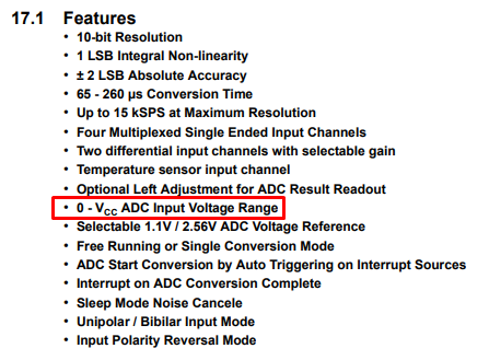
1 Like

Hi Pix,

Hmmm, the signature usually refers to what sort of chip it is, at least in avrdude, so I’d say it’s not finding a chip it knows. Could mean the chip is properly dead :frowning:

1 Like