This is a placeholder topic for “Adjustable Dual Channel Audio Amplifier” comments.
Pump up the tunes!! Use this feature-packed audio amplifier to bring a whole new sense to your projects.
Read moreThis is a placeholder topic for “Adjustable Dual Channel Audio Amplifier” comments.
Pump up the tunes!! Use this feature-packed audio amplifier to bring a whole new sense to your projects.
Read moreDo you have sample Pico code and wiring for this?
Hi Claire,
I found this library to work well with this driver: GitHub - danjperron/PicoAudioPWM: PWM audio on pico with 8KHz stereo wave file
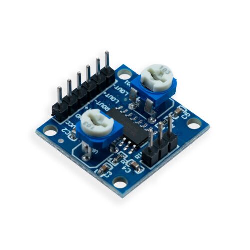
Here’s a quick wiring diagram for the product, I’d recommend going with Enclosed Speaker - 8 Ohm, 5 Watt | Core Electronics Australia for speaker
Liam
Please could you tell me what the maximum output power of the amp is?
Hi Jim
Welcome
As with any Class D amplifier that will depend on input DC voltage (2.5 - 5.5V) and speaker impedance (4Ω or 8Ω).
There should be a chart with that info but I note in this case there is none. You might get some info with the IC data sheet if you can find out what IC is used.
Cheers Bob
Hi Jim,
At 4Ω the output is 3W.
It uses a PAM8406. I’ve updated the store page with that info and the datasheet.
Hi Jack
At what voltage, and is this per channel or total power?
Cheers Bob
My intepretation was total at 5V.

Hi Jim
Now we know what the IC is (thanks Jack) the data sheet tells us this.
That’s great. Thanks Bob and Jack.
In the PicoAudioPWM it is mentioned “For amplifier don’t use PIO4 and the capacitor should be 2200pF and connected to GND.” Does it mean we are just going to connect two 2000pF capacitors from IO2 and IO3 to IO4? What are we doing it for? Is this to address whistling feedback?
Hey @Andrei274211,
The instruction seems to be to place a 2200pF capacitor in between both Pico outputs and ground. The primary case for this capacitor is likely to filter out electrical noise which will typically be at higher frequencies than the actual audio signal.
I must admit I am not sure why this was done on the Pico’s output rather than on the final output, perhaps a unique necessity for the original design which did not make use of this specific Class-D amplifier.
Page 10 on the PDF for the PAM8406 discusses recommendations for various additional capacitors to be used in a circuit for the IC. I would assume most, if not all, of these measures have been taken given the PCB contains 4 capacitors, 2 and adjustable trim pots + resistors. I think it’s safe to assume that the additional circuit elements are not required, though it may be safer to include them regardless.
Hope this helps!
Thank you @Zach! I do indeed have quite annoying howling and whistling with this amp. The Amplifier seems to have some capacitors and resistors and on PCB, but maybe I need to do something to deal with that.
Hi Andrei
Do you have a microphone in the system somewhere.
Cheers Bob
Thank you @Robert93820 , no I don’t have a microphone in the system.
This is the current setup:
Anticipating question about sensors - it howls without sensors in the same way.
Hi Andrel
Try connecting the Audio input ground to Pico pin 3 and Audio VCC Gnd to Pico pin 18 although the Pico Gnds should be connected on the Pico I think. The input and VCC grounds could be separated in the Audio IC. Don’t know.
Cheers Bob
Hi Andrei
Just a further query.
Just what sort of signal are you generating at the Pico output pins.
I think the amplifier input would be expecting analog audio.
If you are generating PWM signals at the Pico outputs you will be trying to digitise digital signals and expecting analog audio at the speakers.
Don’t think that will happen. Might explain the howls and screeches you are getting. Try disconnecting the audio amp inputs and see if the whistles etc stop.
Cheers Bob
Yes PWM frequency of the library seems to be set to 122KHz, which is probably high enough to do the job, but low enough to drive amp crazy.
I assembled this filter which supposed to drain all high frequencies to the ground. And yes, it removes howling.
The setup on the image consists of 2.2K resistors connected to each Pico output, and then 4.7nF capacitors on each channel after resistors connected to ground.
This page has schematic of the filter and handy calculator
The formula to compute capacitance for -3dB Cutoff Frequency
C = 1/(2πR*f)
According to the calculator to roughly cut off everything higher than 15000Hz, the capacitor should be 4.8nF with 2K2Ω(edited) resistors.
(repo recommends 2.2nF, which would result something like 40000 ish cut off)
Please correct me if I’m wrong in my understanding.
Speaking about grounds on the amp, I think it won’t harm, but wouldn’t make any difference.
Look at the photo
Both in and out grounds are directly connected.
Hi Andrei
Yes, they are connected so for DC there is no difference. But I personally would connect input ground to the Pico ground closest to the Pico outputs. Keeps things tidy and minimises any potential interference or feedback possibilities.
I assume from this post that fitting the RC filter on the Pico outputs solved your problem.
For interest what are you doing.
Generating a tone with Pico in response to sensor input.
Using the Pico as a Codec to decode Wav, MP3 etc files for listening.
Feeding Audio into an ADC input to convert to PWM .
I know some do it but the last scenario always seems pretty useless to me. Taking perfectly good audio, converting to PWM (digital) in a Pico, Filtering this to recover the audio (at some dubious quality) then presenting this to this type of audio amp (Class D) which is going to digitise again before final filtering with the speaker circuitry. Over complication at its finest in my humble opinion.
I therefore assume you are going to use one of the first two situations.
Cheers Bob
And you can get our latest projects and tips straight away by following us on:
![]()
![]()
![]()
![]()


