No. C++ is very particular about syntax. See below for correct code.
I have verify compiled the code, no idea if it actually does what you want. You could put a while (1); loop into it anywhere to stop it and take a measurement of the pins. You can put a Serial.println(Generator_ON); line in to see what the Generator_ON variable is doing. Note this will be 1 if true and 0 if false. Replace Generator_ON with any other variable name or use multiple serial.print statements.
To put the text into the box, highlight it in the edit window and click the </> icon in the menu. Click post anyway in the window that pops up when you click reply to add the post.
Cheers
Jim
 if (Generator_ON) {
    if (millis() < Gen_Timer) {
      digitalWrite(GENERATOR, HIGH);
    } else {
      digitalWrite(GENERATOR, LOW);
      Generator_ON = false;
    }
  }
Looks like you’re making great progress, make sure to let us know how you go with the project! If you need links to any specific tutorials or parts, we should be able to get the appropriate links for you. If there’s anything else that you need please let us know!
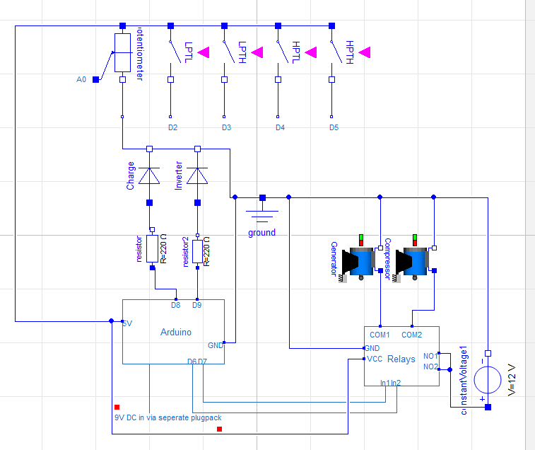
I can get the led’s to light up with the potentiometer. However the relay isnt operating and the switches don’t seem to have any effect. I suspect I am wiring it up incorrectly. Should the switches be connected to ground instead of the 5V rail? Could you have a look at my wiring diagram?
I purchased some push on push off latching (SPST) switches like you suggested. Also something I should have asked but didn’t consider is what happens with the code when no switches are pressed? or the time between pressing switches?
Thanks bryce I may have jumped in too deep too fast lol.
My apologies for being a noob
Also do you prefer Jim or James?
Your schematic shows the switches connect the Arduino pin to +5V when activated. The code looks for a LOW condition so, yes, they should be connected to GND. But I have noticed another error in the code. As I said it was rough first draft with no test against actual components or UNO. This error is what happens when you cut and paste and forget to change it.
Change the following lines. Note the last statement has been changed to false.
Your logic has the Compressor activating when LPT is HIGH and HPT is LOW. Represented by 2 push button switches. Both these would need to be pressed at the same time and held for it to activate. A Toggle or latching switch would make it easier. Releasing either of the switches, the compressor would stop.
When no switches are pressed nothing should activate. The code can be changed to detect a switch press and then keep something going even after the switch is released but it would then need to know when to turn it off or it would just keep running forever.
A minor point.
If this was my design I would connect 12V to the Common terminal and the fan to the Normally Open terminal. This would allow the relay to switch 12V to the Normally Open or Normally Closed terminals.
But it is unimportant when not using the other terminal.
I had wondered about those lines of code. I thought perhaps they were meant to hold the switch condition when it was not pressed but that was my next question. Thankyou for clarifying!
If you are uncomfortable accepting any compensation for your time. Would you accept a gift certificate for your input?
I seem to be having an issue getting the relay signals to go low despite the combination of switches they always seem to be high. It is probably my fault for wiring it up wrong and possibly frying the arduino board. Will try the other board I purchased and see if that was the issue.
Don’t worry about email address; really don’t need anything, just happy to pass on my knowledge and experience.
From your last email, I gather the new board works but the old one no longer does.
Did the old one work at one time, but now dead ??
If that is the case then don’t use the new one until you find why, it may go the same way.
To test the ports on the Arduino you could set up a simple program to set the port high for a number of seconds then low for a number of seconds; and have this repeating. Like the blink program. This would be with the Arduino removed from your circuit. You could use a multimeter to measure the pin level and see if it is changing. Or you could connect an LED and resistor. Port 13 already has an LED connected on the board. A 1k resistor would limit the current and still allow the LED to light up. (5mA)
The port pins on the Arduino can provide up to 40mA, but not all at the same time. In practise I limit the current drain to 10mA or less, using an external transistor if I need more current. Depending on the interface an inline resistor could be used to protect the pins. (220 to 470 ohm)
The dual relay you linked has a digital input, which should be ok connected direct to the pin. I would need to see the circuit diagram to be sure. You could test the relay and measure the current it requires without connecting it to the Arduino.
*** Important ***
The relays provided in the kit do NOT have a digital interface !!! The Arduino pins need protection if driving these relays. It would be best to use a transistor to drive them. They also need a back EMF diode across the coil. But maybe you are not using these.
The Arduino is fairly robust but can be easily damaged.
Anyway, happy to provide circuit and / or code to test if you need.
Hi Jim
I suspect I damaged it by connecting LED’s and forgetting the series resistors initially. But i’m not sure =(
The second arduino I used seemed to work perfectly though.
Thankyou for the relay link. I also had issues with he included 9V battery in the Elegoo kit. The voltage got so low that it seemed to have issues running the relays which was part of the problem. Although it likely drained during the prior tutorials where I used it. Knowing that there is a separate VCC voltage input for the relay is very handy.