What number crimper do the JST SM and the XH pins use?
I’ve tried 2 different crimpers that online descriptions say they are supposed to use and neither one will work, they just destroy the crimps, I tried both the SN-48B and SN-28B and have a set of SN-01BM on order now to try.
Thanks
Hi Kevin
Agreed these crimpers are mostly very difficult to use. Most videos demonstrate (and make it look easy) a method whereby you put the crimp into the tool and start the crimping process to hold it in position. then the wire is inserted and the crimp completed. That is all fine and is the easiest way to do it.
BUT in Australia most hook up wire you purchase is rated for our 240 (or 230) VAC mains and the requirement here is a minimum insulation thickness of 0.6mm which is thicker than most other countries including USA where a lot of these videos originate. This makes the overall diameter considerably larger and I find it near impossible to insert the wire properly into these connectors as per videos. I think this is where most of the problems lie. you have to lay the wire into the tool before trying to put the whole lot into the tool. this can be very difficult and frustrating. If your pins are on a strip remove them while leaving the little bit of the strip on the back of the pin until after the crimping process. This leaves something to hold with the wire in place while starting the crimping process and makes it that little bit easier.
Another problem that can crop up is if the hole on the connector is a bit small the thicker wire will not go in easily even though it is crimped correctly.
An alternative is to try and source wire with thinner insulation but such wire MUST be reserved for low voltage use and NEVER used where 240V mains are involved.
The pre-made wires with pins and connectors fitted would have been done on a machine but even these are not infallible and I have often found faulty crimps like crimping on the plastic.
Cheers Bob
PS: When I was working we often used equipment sourced from USA and to be compliant all the mains wiring had to be replaced as the insulation did not meet Aust requirements.
1 Like
Hi Kevin,
If you’re going to do a lot of crimping, I suggest investing in a pair of Engineer brand crimpers. I used a pair of PA-21s to crimp probably about 100 JST XH connections with no problems.
My technique was:
- Get a clean cut at the end of the wire
- Strip about 2mm off the insulation at the end
- Use the “1.6” setting to crimp around the wire
- Use the end of the pliers to bend in the insulation legs a little
- Use the “1.9” setting to crimp around the insulation
Example video
If you are struggling with thick insulation, and are working at ELV, then PTFE/Teflon coated wires tend to have thinner insulation.
Please let me know if you have any followup questions about my experience, as I’d love to save you some frustration if possible.
1 Like
HI @Robert93820 et al,
My Dad used to work in the SA Electricity Trust test labs, and an immediate ‘fail’ on equipment - especially imported gear - was the insulation colour on the 240 V wiring. The correct standard is
- active - Brown
- neutral - light Blue
- earth - Green with yellow tracer
Why? these colours are appropriately different for colour-blind people, with the most common colour blindness in males being RED-GREEN - i.e. unable to distinguish between the Active and the Earth wire in the old scheme where active was red, neutral was black, and earth was green.
And a second easy fail was an incorrect earth wire to frame connection. The earth wire from the supply cable should be immediately bonded to the frame, and NOT go into a terminal block, then to the frame.
Murray
1 Like
Another good reason for making the mains cable colours international. Back in the 60’s a friends brother killed himself because of that. He had purchased a hair dryer from Asia (He was in the Navy) somewhere and changed the power plug himself. Trouble was the earth wire in that particular country was Red. you can guess the result. Fatal.
USA can be a bit of a bother too with their Black and White wires, Black is Active.
Cheers Bob
2 Likes
And I have seen some German equipment with two black wires, and a white - one black wire had a fine white trace on it - that was the active, and the white was the neutral … another easy one to get very wrong.
sigh
Murray
1 Like
Mine aren’t house mains, they are really small wires in a 3d printer, like for the fan connections and the thermistor and other connections, nowhere near big enuff for house stuff,lol
They are low voltage, 24v dc with less than 10amps or so going through them… lol
I can add a picture of one if needed to be able to get a sense of the sizes of them, they are SMALL,Lol
Thanks for all the information so far and I’ll check into the crimpers the one guy commented here and see if they will work for what I need.
The pins are 2.54mm from what the description says on them, small… lol
Thanks
1 Like
Hi Kevin
Realise that. I was just pointing out that most wire sold in AUS will probably be rated for mains (the manufacturer does not know the intended use) and he manufacturer will produce his wire to be compliant with this scenario to be on the safe side.
I have just found this type of wire to be pretty difficult to terminate with a ratchet type crimper and these small connectors.
If you are re-terminating existing wires it is quite feasible that they may have the thinner insulation and the terminating method outlined above will be OK.
Cheers Bob
1 Like
Ahh, gotcha,lol
Still appreciate all the information and help.
Thanks
TV LED Strips could be a good light source but I don’t recognize the connector

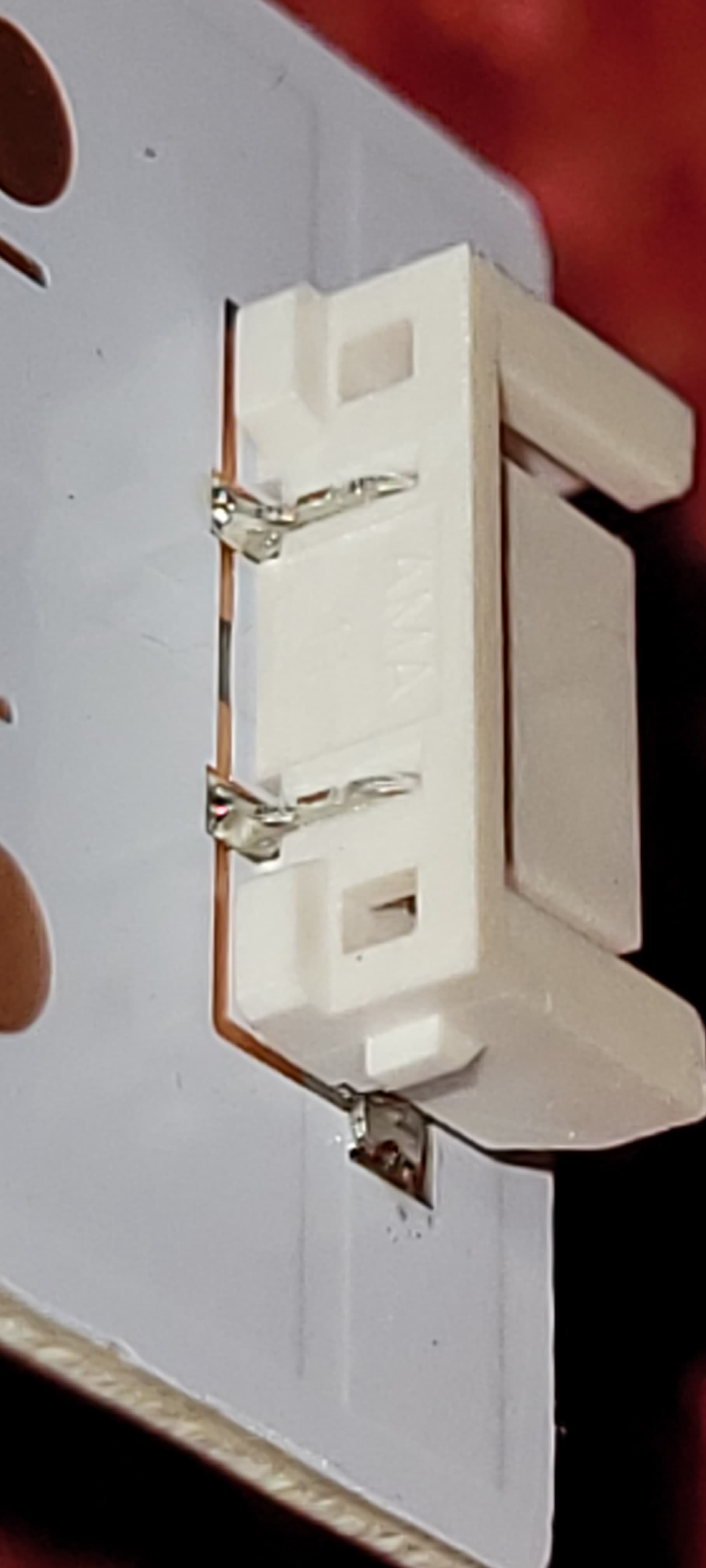
It is a 5mmx9mmx3mm 2-pin SMT connector. Contact pitch is 3.5mm
Anyone know who makes this connector - I am looking for the cable end.
Hi Mark,
Unfortunately that’s not a connector I’ve come across in my travels (apart from seeming to be made from a same-coloured plastic to certain JST connectors) My personal recommendation if nobody else can identify this one would be to desolder the connector and solder wires directly to the pads on the LED board, and provide some strain relief so the solder joints aren’t stressed in any way (hot glue, zip ties work in a pinch).
Hi James, Mark
If you are going to solder wires (by far the easiest solution) leave the connectors there to minimise risk of damage when trying to remove. Just solder the wires to the connector contacts on the rear of the connector. Then pass a small cable tie through one of the square holes I see in the back to secure them.
Job done.
I assume this is DC so if you use a Red and Black wire for identification make sure they go onto the correct connector contact.
Cheers Bob
1 Like
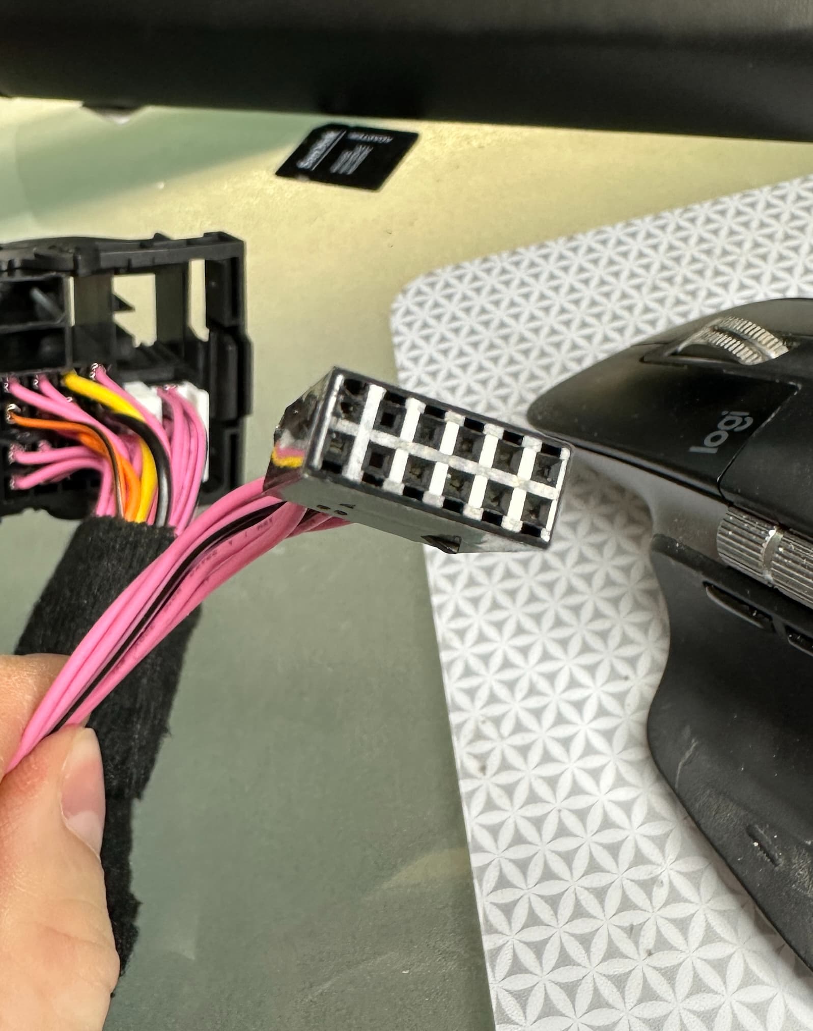
Hi everyone,
Would anyone be able to help me identify this connector please?
I bought a spare battery for my son’s AC toy but I got a different connector…
Many thanks!
Steph.

Welcome Steph.
That is a new one. Could you post a Pic with the numbers on the battery in focus, that might (or might not) help.
Cheers Bob
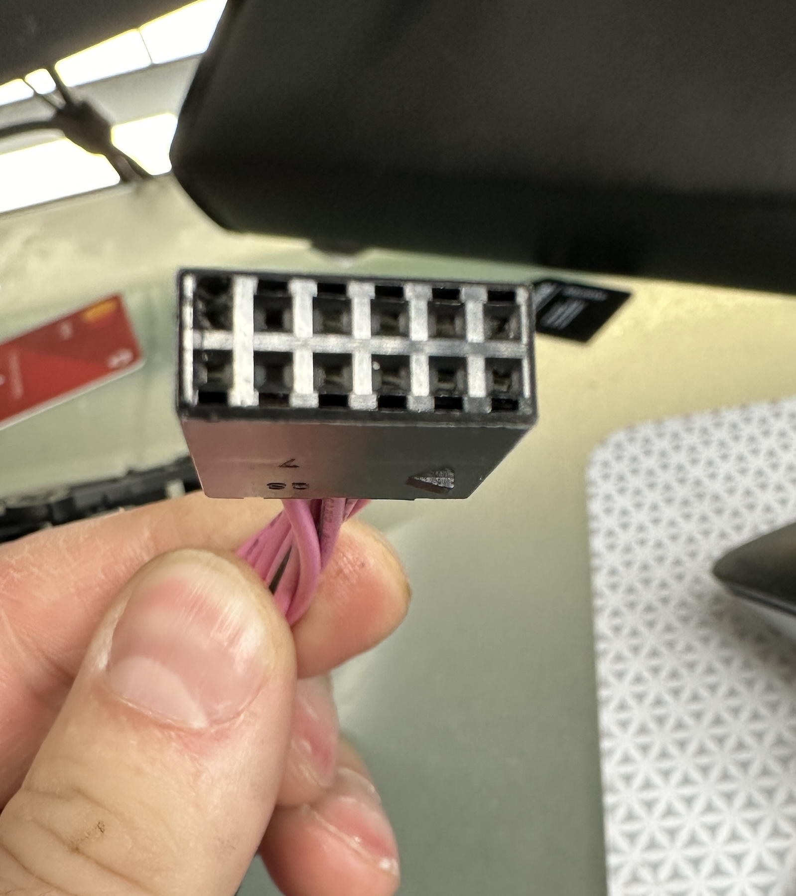
Also the physical size of the connector with a pic of the connector sitting alongside a ruler might do to get some idea.
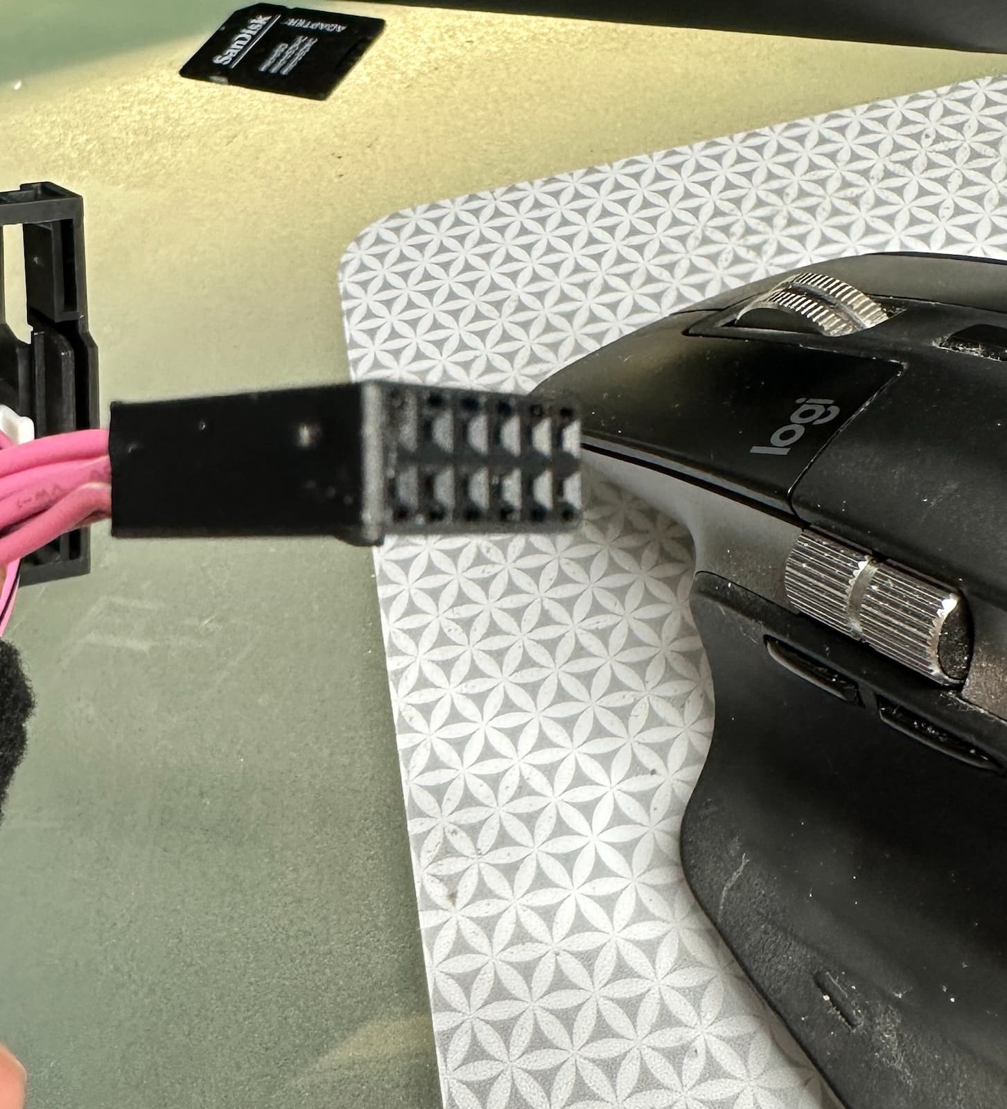
Thanks Rob,
Here it is:

plug pitch is 2mm. I suspect this is an MX 2.0 but not sure.
Rgds,
S
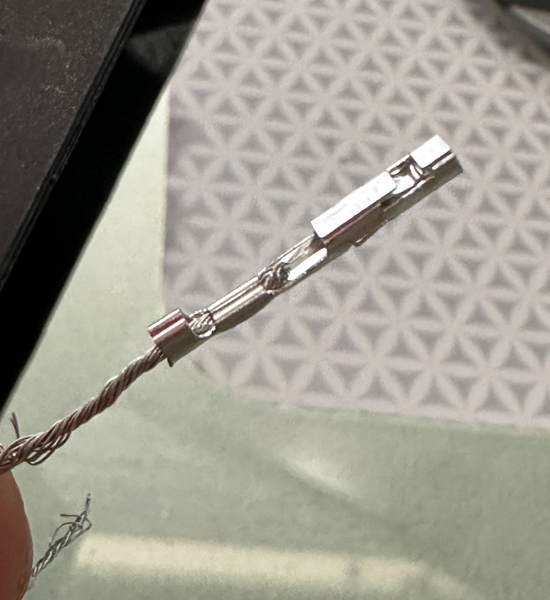
I have a connector that I am searching for that goes to a record player. The company that makes the record player still exist but is not the least bit helpful. Instead of sending me the complete wire harness they just sent me a bag of the bare wires. Anyways, the harness is a 5Pin connector that uses super thin wire for the tone arm. I’m guessing something like 32 to 36awg wire. At this point in looking I have no clue if it is a type of JST or a Molex. I have a picture of the plug that is on the main board.
1 Like
Hi Michael
Record player might have been made before JST came around.
Where is the pic??
Cheers Bob
1 Like
I didn’t see a spot to attach one. Record player is the Floating Record Player by Gramovox from 2015.

1 Like
Welcome to the forum Michael!
Thanks for sending that photo through. A key detail in Tims guide is the connector pitch, would it be possible to send through that measurement (the distance between the center of 2 adjacent pins).
Liam