I am using a Multicomp Pro MP750510 Arbitrary Waveform Generator (AWG) and want to generate a 5-cycle sine wave burst from an external trigger.
The external trigger is a 200 Vpp, 150ns negative square pulse which I have brought down to fit the trigger requirement range of the AWG using an attenuator.
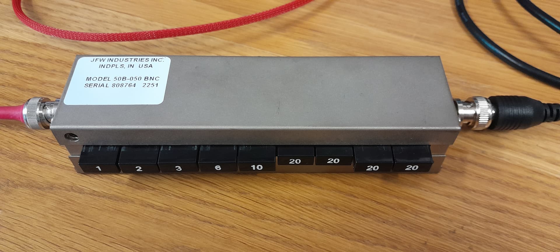
I am using a 1db step attenuator, and have tried 0.9V, 1V, 2.4V, 4V and 5V square pulses with the same pulse width to trigger the machine with no luck.
I have gone into the AWG’s counter setting to monitor the frequency of any external inputs and have detected nothing.
I have manually triggered the 5-cycle sine burst and have checked the correct wave is produced when triggered.
I have set all CH1 inputs to external and tested every gating and slope polarity.
I cannot trigger the wave from the negative square pulse, despite trying a range of voltages.
Is there something I am missing or could I have faulty equipment? Is it best if I try and test another AWG?
Here’s a link to the generator datasheet if needed
I think the word “negative” is a clue here. The spec says TTL compatible. The last time I looked this was a POSITIVE pulse.
You might have to send it through a capacitor to remove the DC component then an inverting comparator to convert to a positive going pulse. This done at the lower voltage level.
Cheers Bob
I’ve used the exterior input, labelled Mod/FSK/Trig.
Unable to send a photo at this time, but I will be able to at some point in the next week if its still helpful
That’s a good point, however, I tried to self-trigger using a positive and negative square, spike and arbitrary wave on CH2 to externally trigger the CH1 output with no luck.
I will consider the inversion, but I don’t want to apply it until I know it works, which I am unsure about as I can’t even self-trigger it with a known, modifiable waveform.
I am suspicious it is an issue with the AWG.
Hey Robert!
Sorry for the late reply, I’ve done a bit more R&D and found that you are right! I’ll need to convert this to a positive pulse.
Any tips or guides you can point me towards to help make the “flipping” component? Looking at around 3V lower voltage level, I’m not sure what capacitance I’ll want to use or where I’d source and implement an inverting comparator.
I’ll do some research myself but I’d appreciate any help you can give!
Hi Noah
I am a bit late also. A few chores needing attention.
Got a couple of ideas and will put pen to paper or finger to keyboard in the next few days.
A couple of points to clarify.
The existing pulse is negative going WRT Gnd, 150nSec wide. Is this correct.
Do you know what this looks like. That is it a nice rectangular pulse or a spike of some sort.
What is the cycle period. Is it repetitive or random.
I just had a look at the AWG specs and the trigger pulse is required to be >100nSec. If your pulse loses a bit of shape in translation it could be border line. It may require re shaping which might involve a LM555 IC which will have the advantage of the width being controllable easily.
Do you have or have access to an oscilloscope. Would ideally need to be 100MHz bandwidth or if less you need to be aware of some limitations when measuring.The reason being if that 150nSec was a repetitive pulse stream that would be about 6.6MHz fundamental frequency. A rectangular waveform is made up of this fundamental and the odd harmonics out to somewhere like 9, 11, 13 for a good fast rise tome. That means a requirement of something like 70MHz bandwidth for all your manipulation if you want to maintain shape. The same goes for the instrument you use if you want to believe what you see.
If you can clarify the queries above I will post a couple of circuits for you to play with.
Cheers Bob
Its pulse repetition frequency can be set between 10 and 1000 Hz, but for my use, it needs to be read by the AWG at all frequencies in this range.
The oscilloscope is a Multicomp PRO MP720011, 100MHz bandwidth.
I’ve just tried using a simple inverting amplifier using an LM741 op-amp and two 51-ohm resistors and have noticed no change to the waveform except a stabilisation of the initial spike.
Happy to provide FFT details for the harmonics, but I can only find the fundamental before it falls into noise.
Let me know if there’s anything I’ve missed
You originally said 150nSec. That is a hell of a long way from 5µSec.
The screen says 800mV P-P which will include the spikes which might not exist in the real world, that is they could have been introduced by the probes or anything.
The pulse appears to be completely negative going. so we are going to have to do something about that.
The 51Ω is too low for that application. To invert that signal you would need a split power supply like + and - 5V or more. To use a single supply we have to move that pulse up into the positive region.
Not too difficult but somewhat more than 800mV (or 500mV if you ignore spikes) will be required.
That will be due to the very limited response of the 741. That OP Amp will be no good to you unless you use a supply of about 10V. It will not output anywhere near VCC. If you only have 5V available for this purpose you will need rail to rail ICs
If you have used an attenuator to get to this level can you change it to get about 5V P-P. Your AWG spec says the external trigger input is TTL compatible so you will need a pulse of 5V P-P at the end of the day. Could you please clarify this point.
Cheers Bob
Sorry about the pulse width, I’ll need to explain a little bit more about the circuit to to be a bit clearer and recover some mistakes I made in the original post.
I have a device that outputs a negative spike pulse. It has a variable pulse width from spike to 200 ns. I’ve run it through a protection circuit (a combination of resistors and diodes, as it calls for in the procedure I’m trying to replicate) which both drops the spike to a safe voltage for the system and increases the width of the pulse significantly (3-8 µs, depending on the device parameters).
The pulse I must have mentioned in the original post must have been direct from the device and not the processed one passed through the protection circuit designed to be read by the AWG. The processed pulse will be the better pulse to change.
Because of the protection circuit, I won’t be able to use an attenuator for the purpose of increasing the voltage. However, testing the AWG by feeding itself back (correctly now, as I said in the original post it didn’t work), the trigger operates from +580mV to at least +5V, so the spikeless 500mV won’t work unless amplified as well as flipped (which I believe can be done with a difference in resistors)
Is an inverting amplifier the correct way to go about flipping this wave? If so, what op-amp should I use and what resistors should I be getting?
If not, what’s the best approach to flipping this and how should I do it?
I’m not too sure what you mean by split power supply or rail-to-rail ICs, I’m learning a lot as I go to solve this problem. I pretty much want to get this solved as soon as I can so I can move on to using the function of the circuit.
Again, thanks for all your help so far, I’m feeling fairly close to getting this to work. Let me know if you need more details.
Nothing to do with the protection circuit, an attenuator cannot increase the voltage, only decrease it. That’s what attenuation means, reduce something.
true.
No.
Can you elaborate on this "protection circuit, like post a schematic. I am flying a bit blind here as you seem to have gone from 200V P-P to 500mV P-P. I can’t think of much that would require this amount of “protection”
Something to check. You have informed the oscilloscope what prob you are using I hope. If for instance you are using a 10:1 probe and the instrument thinks you are using a 1:1 probe a level of 5V would appear on the oscilloscope as 500mV. This could have happened quite easily (I have done it several times) and you might actually have a 5V pulse.
Actually I hope this is the case as we need something like 5V to get this flipped. It is doable I think with a single supply but not at 500mV.
It is actually 2 supplies connected so the neg of one and the pos of the other are connected to a common ground. So you have Ground, one connection Positive volts and another connection negative volts. In early days of Op Amps this was always used but over time Op Amps and techniques have been developed to use a single positive supply.
These are ICs that can swing the output from a few mV above ground right to within a few mV of the supply rail. Usually Mosfet outputs which have a very low Drain Source resistance when fully ON. Most common amplifier devices only get to within about 1V - 1.5V of the supply.
By using such an Op Amp as a comparator we can get almost a full 5V pulse which is what we want for reliable triggering of your AWG.
I think it is the only way. If you can clarify the points above particularly re the 500mV or 5V and the “protection” circuit I think we can get somewhere.
If it happens we are stuck with 500mV you will need a split supply.
Cheers Bob
Hi Noah.
I just drafted a lengthy reply to this but I am not allowed to post it.
I finish up with this:
I don’t know what part is at fault but apparently I needed to repeat myself somewhere. So sorry, unless Core can tell me where I am going wrong I don’t know what part to reword.
Sorry 'bout that
Cheers Bob
PS I have it saved if there becomes any way to post it.
Hi Noah.
I have a reply drafted but am not allowed to post it as it seems it is similar to what is already posted.
I don’t know what part is causing the problem and until Core can tell me I can’t reply.
Cheers Bob
I don’t know exactly what happened there. Firstly I could not post the reply and got a pop up message as the screen shot above.
Then after some more attempts to explain I found that all had been posted and I had reached the consecutive limit of 5.
Something went wrong and then righted without me knowing but all seems in order now.
Cheers Bob
Hello Robert!
I hope you had a good weekend.
I’m sorry to hear about the complications with the forum, I’ll try to be as clear as possible.
We’re getting a variable attenuator to replace the protection circuit, so I’ll be able to keep the voltage between 3-6V, and changeable.
The protection circuit was given in the procedure. I don’t think the procedure accommodated the sensitivity of the AWG, and now that we’re using an attenuator I don’t think we’ll need to worry about the protection circuit. (I’ve been in touch with the procedure publisher, and an attenuator is a viable replacement for the protection circuit).
We haven’t gotten the exact attenuator we’ll be using, but here’s an image of another attenuator in place of the protection circuit
Do remember this is NOT the same attenuator that will be used, but I’m expecting a similar result. This is using 42dB and the correct probe and CRO settings, I double-checked.
Now we need to flip the wave, removing the error with the protection circuit (which also caused a few user issues with the 10:1 probes as you thought, sorry!). I know how to assemble an inverting amplifier, I just don’t know what op-amp or resistors to use for 3-6V (4.8V for this case, there will be a range of voltages in other cases which is why I’ve opted for the variable attenuator).
If there are a few I’ll need that’s alright, it’ll cost like $0.50 from JayCar anyways so I’m okay holding a few different ones for different cases.
Hi Noah
Having an oscilloscope is a huge help.
You seem to have lost the pulse stretching and back to ≈ 200nSec at 4.8V. That could be a bit of use.
The pulse shape:The poor rise time is probably the use of a 1:1 probe which will have limited bandwidth. The advantage of using the 10:1 probe is you can realise the full bandwidth capability of the oscilloscope.
BUT, the probe compensation has to be adjusted properly.I don’y know if you are familiar with this procedure but it is fairly simple. I don’t know what flavour that oscilloscope is or it’s bandwidth but you can optimise the operation as follows.
EDIT: Sorry I do know what flavour your oscilloscope is. I just went back a bit to find out.
The end that attaches to the oscilloscope with a BNC connector should have a little box with a small screws adjustment (this is actually a variable capacitor). If there is no little box this adjustment will be in the actual probe body.
Select 10:1 on the probe and also on the oscilloscope. DO NOT use 1:1 on the oscilloscope.
Select DC coupling
Somewhere on the front there will be a square wave calibrate signal. Connect the probe to this.
Adjust the variable cap for a nice square shape with no overshoot and no rounded corners.
What you see then should be a fairly good representation of what you actually have.
Can you carry out the above and post the screen shot of your trigger pulse with a correctly adjusted probe compensation please. That way we will know pretty much what we are dealing with.
With the pulse completely in the negative region WRT Ground you can’t just use an inverting amp with a single supply. It will have nil output. To do it this way you would need a split supply as above. Or I have found a Core product that might just help out.
Charge Pump Voltage Inverter: 1.8-5.3V, 60mA
If the pulse turns out to be a nice healthy square wave there might be another way with a single power supply. Will probably need a bit of experimenting on your behalf but I think you are up to that.
I will post a circuit of my idea when you show me the pics with 10:1 probe.
Also can you post a screen shot with the oscilloscope set to AC coupling. That will give me an idea of where the average voltage sits.
Thanks Cheers Bob
Can we have some details on EXACTLY what this “attenuator” is please.
The numbers don’t add up.
Firstly I am not going into any detail about the use of decibels (db). Suffice to say that a decibel is a POWER ratio and only holds true for voltage if the input and output IMPEDANCE is the same. For instance a transformer with a voltage step up of 2 times is often misquoted as having a 6db GAIN. A transformer is a passive device and as such can have NO gain. Enough said.
Having got rid of that bit lets assume your case has equal impedances and db is valid.
42db is a division or multiplication ratio of 126. Now 200V divided by 126 comes in ≈ 1.6V. NOT the 4.8V you measured.
As an attenuator you will need a 40:1 division ratio which you could get close with a simple voltage divider of 82kΩ and 2kΩ. The 82k should be a 1W type. You could get closer with 39k and 1k but your 39k would have to be at least 2W which is a bit hard to find. Jaycar have the lower wattage higher values.
Cheers Bob
I checked the AC coupling for channel 1 on the same pulse and it was exactly the same
I am not too worried about the dB values (I know it gets complicated fast), the attenuator is only being used for the voltage drop so I’m less concerned about what the values are as long as the processed pulse magnitude is greater than 1V and less than 10V.
The attenuator that I’m currently using is as follows:
This configuration is the same circuit as the image shown on the oscilloscope in this post
It is a calibrated attenuator, and will not be the same one we’re supplying for this purpose. We’re getting a simpler attenuator to replace it as it is only for the voltage drop to be within the AWG’s range.
Being not fully sure how an attenuator works, I don’t know if the wave will be the same with a different attenuator, but that’s a risk I’ll need to take.