I have just shared a new project: “PiicoDev Schematic System”
Introduction:
Hi everybody. Over the past few weeks, I have been working on an intuitive system that makes working and tinkering with the Piicodev ecosystem even easier! Everybody interested in electronics knows about the universal circuit symbols,…
Read more
This brings a tear to my eye ![]() What a wonderful contribution to PiicoDev @Ezra224017
What a wonderful contribution to PiicoDev @Ezra224017
The initiative you’ve taken to create a standard documentation format is admirable!
I’m adding your PiicoDev Sketcher schematic to the live project right now! ![]()
Hi Michael! Thank you for saying that. I am glad to see that people have already begun to utilise my system within their projects - you have made my day!
This is so cool!
Something like this could really take off in education ![]() (in my opinion).
(in my opinion).
Hi everyone. I have just finished working on the Fritzing parts for the Piicodev Schematic System! Now, you can download individual parts or the entire bin of Piicodev symbols, including the cables, and create schematics on Fritzing. Here is the link: piicodev-symbols/Fritzing at main · ezradevs/piicodev-symbols · GitHub
Enjoy ![]()
Ezra
Awesome to see this going further ![]()
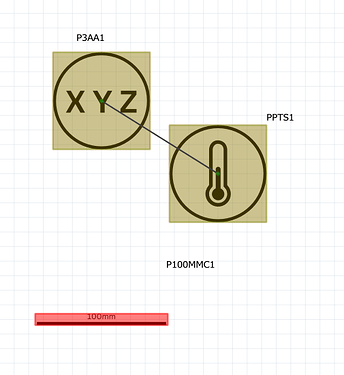
FYI when I download individual parts and add them to fritzing this is the experience I see - there are no clear ways of joining the modules. Is it intended to just position them spatially and join using the cable parts instead of using Fritzing’s connection scheme?
Also!
I’ve made a new PiicoDev Community Contributions article that features this project, and your repo. The idea is to celebrate community contributions in one spot, and make them easier for other users to find
Hi Michael. I appreciate the mention in the article!
I did debate upon using the Fritzing connection scheme, having made a few parts accordingly as depicted in the image below, though ultimately decided to join components with the different cables I made parts for - plus, I think it looks cleaner, and will help users if the project they are working on requires Piicodev components to be spaced out more. For instance, in your Sketcher project, the accelerometer needed a longer cable to be mounted on the back of the OLED module.
Ezra
Hi @Ezra224017,
I am old and new to this world, apologies if my question might be out of place. I started off in electronics, moved to higher-level hardware (IACS), and 20 years later am back.
My initial question was do you mind if I port a copy of your templates into a draw.io library? Draw.io can save a library in a git repo, so I would fork your project, migrate templates in, and then send a PR back.
Fritzing looks interesting, and I will definitely play with this as well. Apart from my own familiarity with draw.io, it is also very easy to access in a school context (I am a high school teacher now, and while I am alive, I would like to see more rigour in school STEM… I mean, when I was in Year 8, pre-internet, we were making and soldering small RC circuit boards at a school club and my friends and I had taught each other QBASIC for writing ASCII games… <falls off soap box>).
Ezra has licensed the repo using the MIT license - it’s open source @Gary127375 ![]() That’s your green-light to go for it.
That’s your green-light to go for it.
Hey Gary! I love your idea of a Draw.io library.
As Michael said, go for it! My project is entirely open source under the MIT license, so go ahead and fork the repo then create a pull request with the library, and I will merge it.
I too have a desire to see more STEM rigour in Australia’s education system, and I am glad you have thought of a way to make my system more accessible for that space ![]() - I am also glad that Piicodev is making its way into schools!
- I am also glad that Piicodev is making its way into schools!
Awesome, I’ll sort out the mechanics in draw.io and send a PR when its ready.
Thanks ![]()
Great ![]() Here is the link to the repo in case you need. Can’t wait to see what you create.
Here is the link to the repo in case you need. Can’t wait to see what you create.
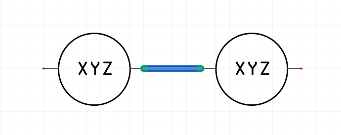
PR Sent with some screenshots in the PR. I would like to do better, but it works well enough for the moment. I also added a README file to the PR which references back to the Project page on Core-Electronics site and started added some very brief instructions for the Draw.io.
Hey Gary, it’s looking great! I’m impressed by the effort put into this.
One thing - I cannot seem to get the dynamic connections working without massive arrows appearing. Would you walk me through how you implemented these, and how I can get them to work?
Cheers
Hi @Ezra,
A picture paints a thousand words…
The video is about 3 minutes longer than I wanted, but it will do. Currently in Low-def as YouTube is still processing the HD version (will be done in 30 minutes).
Cheers,
In my rush and not reviewing the video I realised I accidentally said “when I created these” when what I meant was “when I ported these”.
It is subtle, but I’ll try and fix it later.
Hi Gary,
Thanks for that much needed clarification - maybe it would be prudent to modify the README in your PR with either your video link or the instructions to remove the arrow for users who are unaware? Either way, I love the addition to the project, and it is looking fantastic!
Awesome work @Gary126657 and great dev video to boot ![]()
![]()
For the beginners in the crowd it would be awesome to see a step-by-step in the README.md on how to add the library to Draw.IO
Hi @Michael, @Ezra224017
Agreed, I do have a space for screenshots to be saved on my local. I will aim to update soon and will also make some video updates, all will be added to the README.md file.
Cheers,
Gary
Hey Gary,
Great, much appreciated. Once you’ve finalised that, shoot us a message and i’ll merge the PR.
Cheers


