This is a placeholder topic for “Prototyping Kit for Raspberry Pi” comments.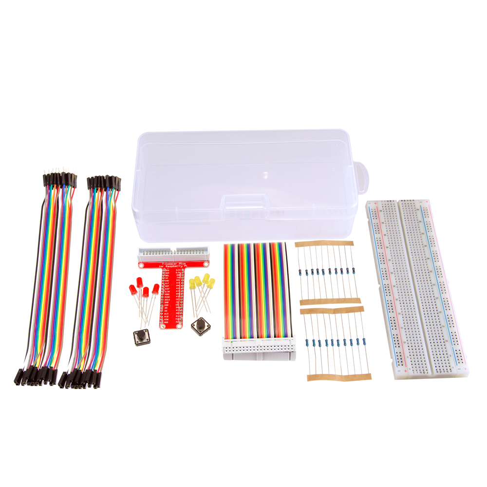
Everything you need to start prototyping and experimenting with the Raspberry PI’s GPIO headers and physical computing. It even includes a handy case to keep your project in!
Read more
2 Likes
I want to build a renote control that needs to be on a long cable - from pi on desk to remote on bed across the room. Going to be 4 + 3 + 3 + gnd so 11. what’s the best for a 4m cable? I’m reluctant to use ribbon as it will torque the pi when moved, but is it my only choice to go from Pi pins to a box with the buttons on?
3 Likes
Hi Zebee.
Quite some years ago there was a cable that would suit your requirements. To all outward appearances it looked and handled like regular round cable, but periodically along its length there was a flat section rolled up within the round sheath. If the cable was cut at these points a IDC header type connector could be fitted. I think from memory the individual pairs were twisted between flat sections. I think it simply was called “Flat/Round” and was screened for good measure.
I think Hartland was one manufacturer. It may be a bit unusual these days but you may have some success with Element14 or RS Components or even the cable manufacturers.
I don’t know how you would go with small quantities though.
If you want to use a header type connector I don’t think there is anything between 10 and 16 pins (2 X 5 or 2 X 8).
Cheers Bob
3 Likes
Bob,
I’d forgotten about RS… I’ll have a look. I’m not too worried about it being ribbon cable as such (although that cable sounds perfect) but something with enough cores. Jaycar have a 6 core alarm wire by the metre that might work, just have to use 2 of them.
If I go that way I guess I have to do a lot of soldering to connect the switches to the wires and the wires to a header that can connect to the pi. I suppose if I can fit a chunk of breadboard into a small enough box I can wire that to a connector (eg a VGA D connector) and attach the cable to the box that way.
The alternative is the pi on a long extension cable and a ribbon to the remote but the ribbon will make a small remote awkward to manage for someone with weak hands and who can only use one of them.
In my dreams there is some way to make a wireless box with switches… I tried to repurpose bluetooth controllers but they are either one switch (phone camera remotes), multiple but the buttons are too small and stiff (steering wheel media remotes) or won’t pair to the pi (fan remotes, light remotes). I have seen some that might work but at over $100 I don’t want to find they won’t.
Finding something a disabled person can use is impossible but building one is hard too! Can’t use a phone because everyone who writes phone software reckons the user has excellent eyesight and a good memory for teeny icons. And can reliably touch the icons.
3 Likes
Would this be of any help? I do not know if Core carries this product, but it is a dock for Pi with protoboard in a single template.
This is another Pi Hat, that might be useful.
I found another remote, which can be used - apparently it is programmable and compatible with Arduino - might be possible to use them with Pi and appropriate microcontroller addition.
All the links are from pishop.us, but Core might have them or point you in a right direction.
If you are interested in semi-smart controls, home assistant can be installed in a docker on the Pi. TP-Link Kasa is compatible with home assistant. They do have smart switches and smart plugs, which are compatible with the voltage ratings in your locale. An USB mic and speakers added to Pi can give a good voice control.
3 Likes
If you only need one button at a time, I’d take a look at a couple parts listed below. I dont have expereince with them myself but it looks like you can get 16 outputs using the 4 binary channels on them(2^4 = 16).
I’m sure there is a single IC to code and decode on both ends rather than throwing in an MCU or using logic gates.
Here’s the links, you have to buy them as a pair though:
2 Likes
That’s rather intimidating… I need one button to switch the radio on and off, one to change channels, and some way to change volume.
Looks like it uses arduino code and no python library to read it?
3 Likes
Hi Zebee
With reference to my earlier tip on flat/round cable here is a link to DigiKey to illustrate what it is like.
This one is 40 conductor but there are probably other sizes. It would seem DigiKey sell this per meter where others like Element14 or RS sell it in 30M (100ft) or 300M (1000ft) rolls. Other electrical suppliers may have it per M. Anyway, it seems to still exist and this is what it looks like physically.
There is some talk about using a breadboard. If this refers to the boards used for experimenting where components and wires plug in I personally would not us it in a permanent situation. Too big and cumbersome and I would always suspect the connections. I don’t think these are designed for long term permanent use.
I have had many years of success soldering wires to pins by placing the wire alongside the pin to solder then using about 15mm to 20mm heat shrink over the joint to provide protection and mechanical support for the wire. Some of these pieces have been in place for numerous years.
To give it its correct title DE15. These would be probably solder bucket types for your use as crimp tools for these pins tend to be pretty expensive. I have a Daniels AFM8 M22520/2-01 tool which I sort of inherited before I started contracting and when new was about $700. Still a current item bur at the moment at Element 14 $1194. Not in most hobbyist’s tool kit. That is without any pin locators which are probably something north of $150 each. For only a few pins I use it without a locator, OK with care but if you were crimping many pins a locator for that particular pin is pretty much a must.
Cheers Bob
3 Likes
Hi Zebee,
The PCB and guides are quite intimidating but the link kit translates the inputs from the transmiter striaight to the receiver. Some simple GPIO inputs(4 on the Pi’s end) can translate straight across using the TX and RX boards, those 4 inputs would be 'unfolded; into 16 discrete states.
There was a smaller one that broke the connections out to pins to headers that you could throw into a breadboard.
Bobs use of the wires would be a much simpler system in the end. G has some excellent points about using a smart system.
2 Likes
Hi! Is the included 40pin GPIO Extension Board compatible with Raspberry Pi 4 Model B? What’s the difference between this and the T-Cobbler Plus V2.2 or the 40-pin Raspberry Pi GPIO Breakout? Thanks!