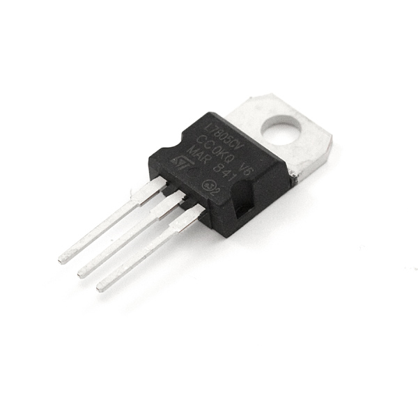
This is the basic L7805 voltage regulator, a three-terminal positive regulator with a 5V fixed output voltage. This fixed regulator provides a local regulation, internal current limiting, thermal shut-down control, and safe area protection for your project. Each one of these voltage regulators can output a max current of 1.5A.
If you need to get more current out of one of these, you can use figure 22 -23 from the datasheet to turn this into a high current regulator you will just need a high current Transistor and a few other components.
Personally I’ve cut back on 7805’s and other linear voltage regulators in favour of the switching type (usually Polulu). Many of my projects rely on battery supply and the wasted power from using linear regulators was too much for me.
Switching Supplies are probably the prefered option in most cases though I have heard they can be a little noisy in some applications. The rational is that due to the square wave output of the PWM it has a lot of frequencies contained in it so you get a lot more resonances.
What is the ambient temperature ?
What is the humidity ?
Is there air flow around the regulator ?
eg, I had a LM7805 on a breadboard, ran ok, ok to touch, put it in a case and it overheated.
Using a heatsink solved the problem (small piece of aluminium, not enough space for normal heatsinks).
You can try and calculate the expected temperature, but it will vary with environment.
In my experience build it and check with IR temperature probe (accurate) or the finger test (too hot to touch).
You need several other data items to calculate likely operating temperature. One is the input voltage, because the power to be dissipated depends on the power difference between input and output. If current is considered the same (near enough for a linear regulator) then the voltage difference determines the dissipation. Then you need to know the thermal resistance junction to air or the thermal resistance junction to case in order to calculate the rate at which the heat can be dissipated to the air, depending on whether or not you are using a heatsink, and adjusted for air flow if you are using a fan. If this is not specified for the component you can take typical figures for the package (eg TO-220). Then you need dissipation graphs for the heatsink you are using.
There is a good example here: Understanding Thermal Resistance - SparkFun Learn
Seems like there are a lot of variables. But that’s ok, I’d be happy with a value +/- 30% of my calculations.
I.e. if I calculate 30c above room temperature an “in practice” 21-39c would be absolutely fine. None of the temps in that range is so hot it will burn you or be unsafe.
Getting in the ball park
Oh that’s what the C/W stands for! Thanks.
Let’s just test I understand this table with an example.’
So for this TO-220 we are expecting 5 degrees per watt.
W = A*(Vo - Vi)
W = 0.1 * 13 => 1.3W
so that’s an additional 6.5c above room temperature.
Maybe as my project evolves I start to draw .4 amps.
That’s 26 degrees which will be warm but still… ya know… safe.
How did I do?
EDIT : This turned out to be wrong, I needed to read the bottom row of the C/W table.
It’s 50degrees per watt…
@Pixmusix looks like you beat me to it as i was formatting my equations I’ll post for posterity anyway.
Dave Jones has a great EEVBlog video from forever ago that goes deep on calculating temperature rise and thermal resistance. Thinking about heat flow like an electrical circuit is a game changer and how it’s really done in engineering.
in any case, let’s do a worked example with data assuming the TO220 is in free air - so we’ll use the junction-to-ambient value for thermal resistance:
R_{thj-amb} = 50°C/W \\
V_{in} = 18V \\
V_{out} = 5V \\
I = 0.1 A
Power dissipated is
P = (V_{in} - V_{out} ) I = (18-5) \times 0.1 = 1.3W
The junction will be 65°C above ambient which is pretty hot!
If you bond the package to a heatsink you can add the R_{thj-case} resistance with whatever thermal resistance data you have on the heatsink which will be much lower.
Actually works pretty well Too hot to touch for me is tuned to about 50°C (plus minus 10 ) which is super good enough for maker projects
OH!! I wanted the bottom row of the table.
Wow 65 IS super hot.
Hmmmm. I don’t want to work with those kind of temps .
If I chose to work with 9V instead. 0.1 * (9-5) * 50 = 20.
That’s much better.
The 5V from my LM7805 will be riding to this makerverse mono amp.
I pulled this graph from the mono amplifier’s datasheet.
So it looks like I should expect draw anywhere form 50 to 300ma.
That would mean the L7805 can go from 10-60 degrees above room at 9V.
Did I get my math right?
Maybe I should use a small heat sink to be safe?
Totally doesn’t hurt
Sometimes you can just screw the TO220 package to the circuit board and use the PCB as heatsink material. Especially if there is a ground or unconnected copper fill beneath the device
Not as good as a heatsink but better than nothing
Yes to both.
Two cheap heatsinks that will probably work ok.
I have used the second one and it makes a big difference.
Air flow around the heatsink also helps.