I am working on building my own head unit, software and all, for my Golf Mk6 GTi. I have been successful in every way except hooking into the CAN bus. I have a CarPiHAT Pro 5, but this HAT uses a VP232 transeiver and MCP2515 controller which only supports normal high-speed CAN up to 1mbps. This makes total sense, but isn’t going to work for my application. Since my car is made by VW, endless difficulties in working with it have popped up - one being the use of the lesser-used Fault Tolerant CAN (ISO 11898-3?) which is terminated differently, looks different on an oscilloscope and can run over just a single wire if things physically break in a vehicle. This FT-CAN is common in German vehicles from what I can gather.
Does anyone have any idea at all how I could interface with this FT-CAN? I believe I would be looking at using a TJA1055 transeiver with a MCP2515 controller to then interface over SPI over the GPIO on the Pi 5. No hobbiest boards seem to exist with this combination. The only FT-CAN tools I was able to hunt down are industrial-oriented, couldn’t live inside a car’s head unit port and are furiously expensive.
If I can figure out this part, I’ll post the whole project on the Projects part of the forum with software, steps and all.
Would it be possible to send through some links so we can cross-check? It’s strange that they would still call it CAN if it wasn’t a differential pair.
A few posts online have mentioned that the head units use standard protocols.
It is indeed very strange. You can find info in the ISO-11898-3 specification. The datasheet for the TJA1055 gives a lot of very useful information as well. Here is a link for that:
It has some very strange behavior even beyond working as a non-differential pair. It is expected the CAN- line (only) will pull up to 12V constant when the line is sleeping for anti-wake up from EMI. When my gateway module goes into sleep mode, the usual 2.45V from each CAN data line goes to +12V (battery voltage) for the CAN- and ~20mV for CAN+… and this is expected behavior. The TJA1055 from what I have read in the datasheet is designed to work this way.
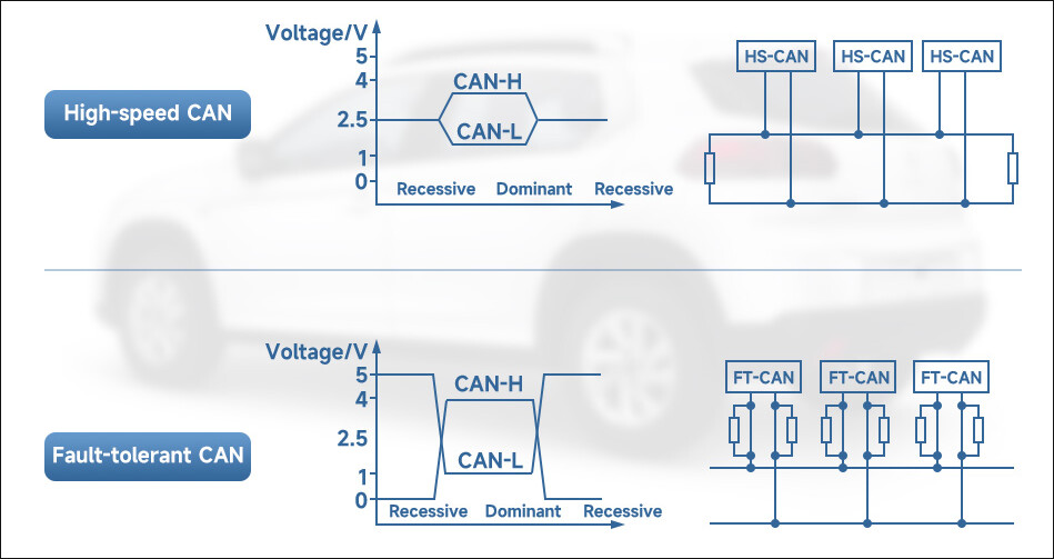
In the datasheet on page 1, they make note of the “Supports single-wire transmission modes with ground offset voltages up to 1.5 V”. The Waveshare USB-CAN-B product page which supports both FT-CAN and regular high speed CAN has a very helpful diagram showing the differences in communication as well:
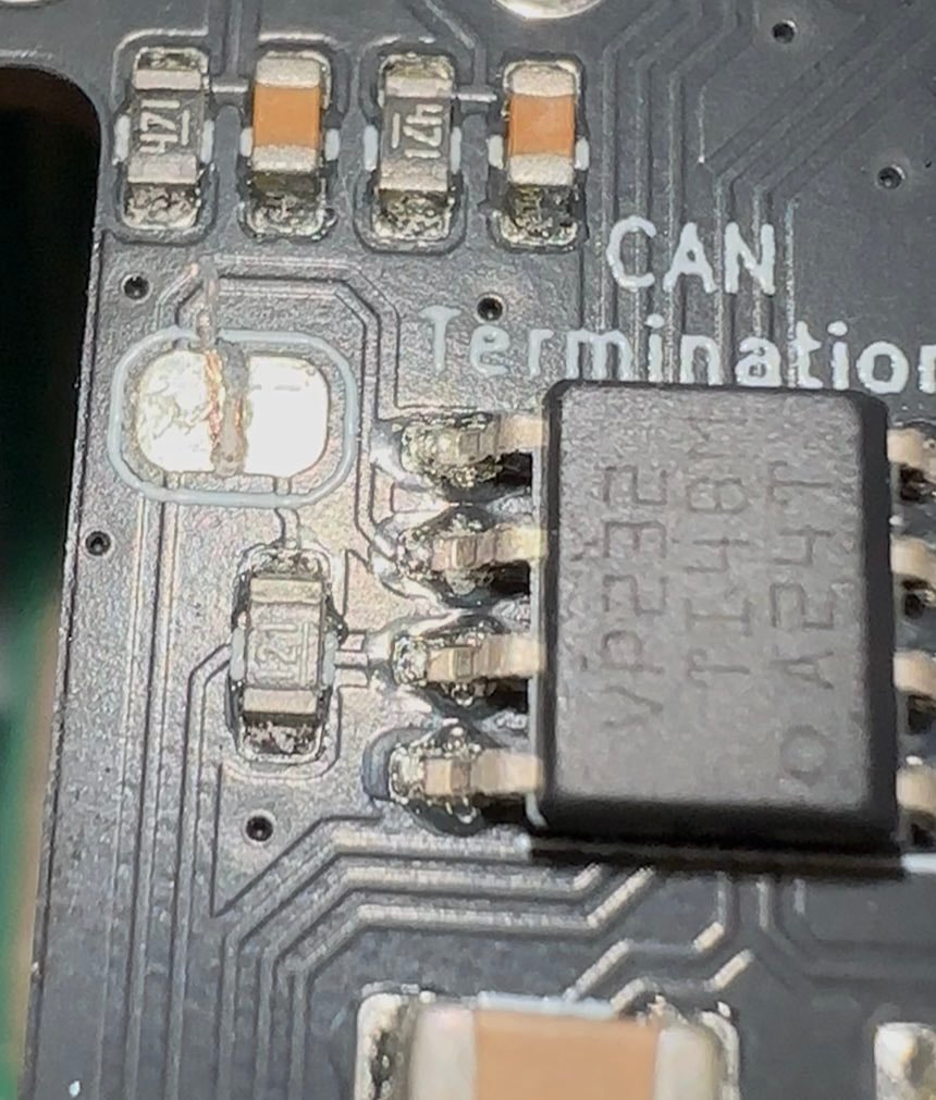
I figured it out, I think. I’m getting CAN frames now. I think you’re right about whoever told me its FT-CAN being full of it. In any case, I had to cut the trace between the termination pads to get it to work. This seems like a serious problem given that I understandably just ruined my warranty. I feel like I shouldn’t have to void my warranty to use an advertised, main feature of this product. It might be worth digging into that. I also had an unfortunate slip whilst doing it. Luckily, I seem to have gotten away with it. In any case, this is the damage you need to do:
I was clued onto this by a helpful fellow enthusiast. The TJD documentation says absolutely nothing about this, but it has supposedly be confirmed by The Pi Hut.
Very interesting, thank you. There’s a lot of very handy info in there.
So I’ve done some digging now I’ve got some communication going and here is what I think is happening:
It is FT-CAN, but VW is doing weird things that aren’t in the usual spec
They’re using proprietary CAN transeivers in their gear that also do weird things
As a result, even though its clearly some weird form of FT-CAN from how it behaves, I’m having zero issues with using my VP232 and MCP2515 with it. I am getting perfect CAN communication now
FT-CAN requires no (or at least different) termination, hence I had to destroy that trace to get frames. Without that trace, I’m getting no reflections and perfect communication. If I ever need it in the future, I can just bridge those two pads with some solder or a resistor depending on what I’m doing and have no issues.
Now I may or may not have a full DBC for the PQ35 platform and through SavvyCAN I may or may not have been successful in decoding all of the incoming CAN frames. My steering wheel controls, steering angle, vehicle speed, reverse light status (feels odd to do things that way instead of reverse gear but okay), etc are all present and correct.
Thus, I’m willing to call this a success. I hope this thread will prove useful for others in the future and I am keen to post my project as a whole in the projects forum when I’m a little further through it.