If anyone is interested this works well in C via the Arduino IDE. I like these displays as they are fast and clear.
You need to flick the switch on the back of one display to change the address from 0x3C to 0x3D.

4 Likes
//Testing using 2 OLED screens at the same time.
//— Oled Screens ------------------------------------------------------------------- Oled Screens
#include <SPI.h>
#include <Wire.h>
#include <Adafruit_GFX.h>
#include <Adafruit_SSD1306.h>
#define SCREEN_WIDTH 128 // OLED display width, in pixels
#define SCREEN_HEIGHT 64 // OLED display height, in pixels
#define OLED_RESET -1 // Reset pin #
#define SCREEN_ADDRESS1 0x3C // Found using scanner. I left the address switch set to off
#define SCREEN_ADDRESS2 0x3D // Found using scanner. I changed the address switch on the PIICODev OLED to on
//Initialize OLED screens.
Adafruit_SSD1306 display1(SCREEN_WIDTH, SCREEN_HEIGHT, &Wire, OLED_RESET);
Adafruit_SSD1306 display2(SCREEN_WIDTH, SCREEN_HEIGHT, &Wire, OLED_RESET);
int t1 = 0, t2 = 0;
void setup() {
//— Screens ------------------------------------------------
// SSD1306_SWITCHCAPVCC = generate display voltage from 3.3V internally
if (!display1.begin(SSD1306_SWITCHCAPVCC, SCREEN_ADDRESS1)) {
Serial.println(F(“SSD1306 allocation failed”));
for (;;); // Don’t proceed, loop forever
}
if (!display2.begin(SSD1306_SWITCHCAPVCC, SCREEN_ADDRESS2)) {
Serial.println(F(“SSD1306 allocation failed”));
for (;;); // Don’t proceed, loop forever
}
//default I2C pins GP4, GP5. These are pins 6 and 7 on the Pico
Serial.println(SDA);
Serial.println(SCL);
}
void loop() {
showScreens();
delay(100);
}
void showScreens() {
display1.clearDisplay();
display1.setTextSize(2);
display1.setTextColor(SSD1306_WHITE); // Draw white text
display1.setCursor(0, 0);
//Display mode
t1 = millis();
t2 = int(t1 / 1000);
display1.println(t1);
display1.display();
display2.clearDisplay();
display2.setTextSize(2);
display2.setTextColor(SSD1306_WHITE); // Draw white text
display2.setCursor(0, 0);
//Display mode
display2.println(t2);
display2.display();
}
4 Likes
Hi John,
Awesome work!! It’s neat seeing the hardware being used with other software packages - Paul and Bob from another topic were asking about using Arduino.
Thanks for sharing!
1 Like
Hi John
Thanks for that
Cheers Bob
2 Likes
My pleasure. Glad it will help someone.
1 Like
Hi John
So you can program the Pico using the Arduino IDE, interesting. Is it much of a hassle.
I have a situation where I am using an Arduino NanoEvery to measure pulse width and would like to use a Pico to do this and drive one of these displays (currently use a 16 X 2 LCD) but I can’t establish if the Pico can do this. I have been through all I can find on the Pico and Micropython but cannot find anything like the Arduino IDE Reference.
My Arduino is 5V (as is the display) so does anyone know if one of these bi directional logic level converters work between 5V Arduino and Piicodev displays or do I need to convert to 3.3V Arduino. Not keen on that. Should read not overly keen on 3.3V
ADA757
CE07510
BOB1209
Pololu-2595
Or the other question will the piicodev display handle 5V I2C
Cheers Bob
One other query. Why do you #include <SPI>.h". Is that required for some reason?
2 Likes
This is the source for the Pico to use the Arduino IDE. It is easy to install and works nicely.
Thinking I may go back to Arduino for the Pico, Micro Python and Thonny is easy to use but does take up too much memory on the Pico.
Regards
Jim
3 Likes
Hi Bob,
Not much of a hassle, you just need to include this link in the preferences:
https://github.com/earlephilhower/arduino-pico/releases/download/global/package_rp2040_index.json
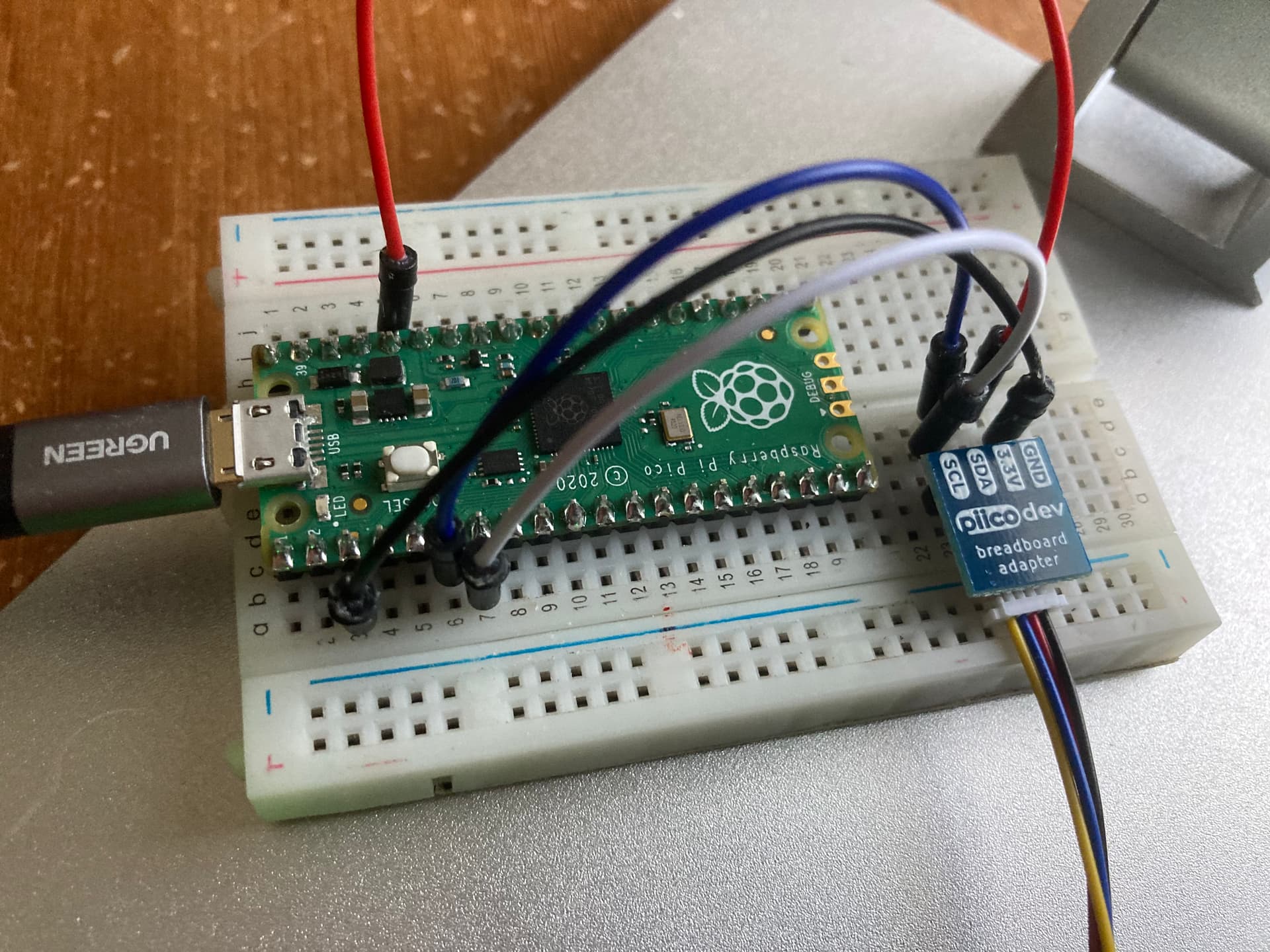
You can see by my photos that the Pico is fine driving the displays.
‘#include SPI.h"’ isn’t required.
Cheers
John
1 Like
Actually 3.3V is fine to use for many things. I have been using Teensy boards for lots of projects and they are VERY powerful and use 3.3V.
1 Like