I have a project where I need to power a Pi 4 using PoE while also using GPIO pins. The Raspberry Pi blog entry that first introduced the PoE HAT (https://www.raspberrypi.org/blog/introducing-power-over-ethernet-poe-hat/) says that you can do it, but that you need a stackable, push-fit 2x20 pin header for the GPIO pins and a 4 pin riser for the power connections. You’d probably also need different height standoffs.
Just to clarify those 4 pins are used by the POE hat to supply the power, there are some other pins in the GPIO that you can get power from. Have a look over at pinout too see what each pin does.
Another one of the POE hats doesn’t have the 4 pin pass through that you might be interested in?
Yes, the issue is that when you replace the low-profile non-stackable 2x20 pin header on the PoE HAT with a stackable 2x20 pin header the spacing between the Pi and the PoE HAT will increase, so that the included low-profile 4 pin header on the PoE HAT no longer makes good contact with the 4 power pins on the Pi. That’s why the Raspberry Pi blog article recommended using a 4 pin riser (that people in the comments said didn’t work…), and why there is a ModMyPi PoE header set that includes a replacement 4 pin header as well as the 2x20 pin one.
I’m not bothered about passing the 4 power pins through the top side of the PoE HAT (i know I can get power from the GPIO pins instead), I just want to be sure I can pass the GPIO pins through the PoE HAT without breaking the power connection between the PoE HAT & the Pi.
No worries, to confirm, this was the particular PoE hat that you wanted to use? Making sure to clarify before checking the datasheets and providing a direct response to the wrong question
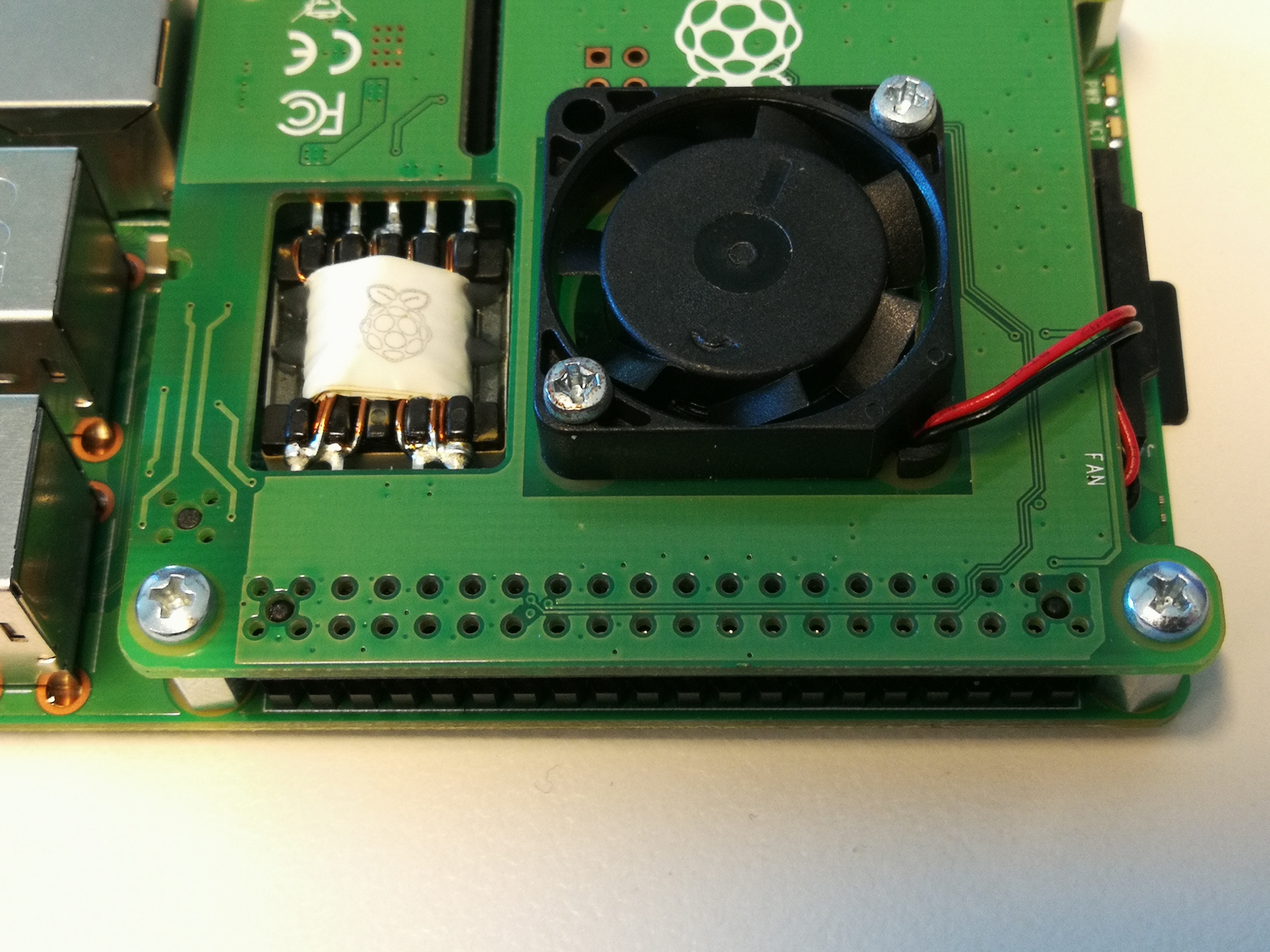
I managed to track down and borrow one today so that I could take a closer look at it. The low profile (~4mm) GPIO & PoE headers are surface mount type, and are not going anywhere.
What the original Raspberry Pi blog articles was talking about, I think, is to use a stackable header with really long pins and put it underneath the PoE HAT, with the pins sticking through the existing low profile header and the PCB (~5.2 mm total) with enough sticking out through the top to still connect stuff.
Something like https://core-electronics.com.au/stackable-0-100-female-header-2x20-pin-straight.html would have about 5mm of pin sticking out the top, which might just be enough, but the 8.5 mm deep header body would end up increasing the separation between the PoE HAT and the Pi by about 6.2 mm, hence the need for a similar riser for the 4 PoE pins.
The ModMyPi PoE HAT header set (https://thepihut.com/products/4-40-pin-pin-extra-tall-header-push-fit-version-poe-hat-set) really does look like the way to do it. 2x20 & 2x2 pin headers with 8.5 mm bodies and super long 14.7 mm pins. You attach them both to the corresponding pins on the Pi, then put the PoE Hat on top. That will leave a decent 9.5 mm of pin sticking out though the PoE HAT. Unfortunately I haven’t been able to find anyone stocking this set in Australia, & I need a solution sooner than international shipping will allow.
You might be able to cut the 2x3 header down to gain access back to the header or swap the sides although it comes into contact with another component on the POE HAT.
Thanks for taking the time to work this out, your suggested solution looks almost perfect!
When I was searched through the 2x20 pin headers I missed the fact that one had removable spacers. With all of them removed it’s basically identical in dimensions to the ModMyPi/ThePiHut ones
The only thing that would make this better is if that 2x3 header came in a 2x2 version, but I’m sure I can work around that. Looking at it I think I’d just need to clip two of the pins off. I assume the pins on that header feel like they make a good connection with the 2x2 header on the HAT?
Yea, in my dig I sadly didn’t come across any 2x2 headers, it seemed like it caught pretty well but wasn’t able to do any testing with it so cant confirm anything for sure.
If you can’t go metric, go imperial! M2.5 is very close to 3-48 UNC. This is an uncommon size, but you may be able to get away with 2-56 (close to 2.1mm) or 4-40 (close to 2.8mm). FYI an M2.5 clearance hole is about 2.8mm so 4-40 would be a tight fit, but might just go.
5/8" is approximately 16mm (15.875mm to be precise). You may need to combine a few different size standoffs but with a bit of creativity you should be able to get there with our shelf stock.
OR, I’ve just checked and it looks like Littlebird have stock of this M2.5 kit in Sydney: