This is a placeholder topic for “Toggle Switch and Cover - Illuminated (Red)” comments.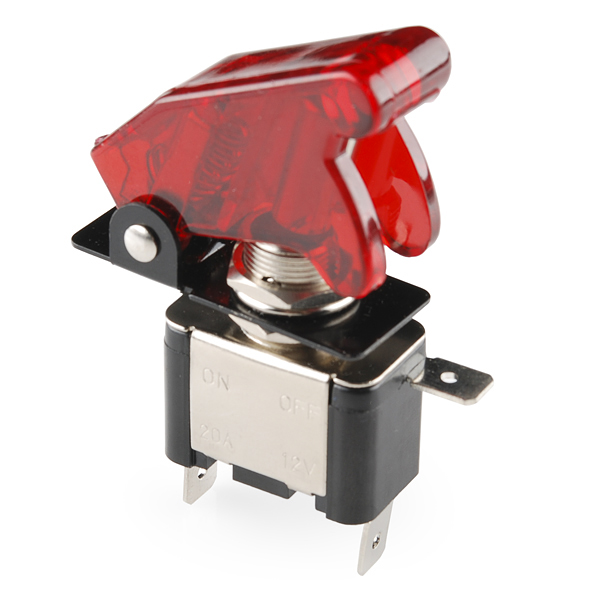
This simple on-off switch is rated for 20A at 12V but who cares about all that, it looks way awesome. These toggle switches come with those missile switch covers that make your project look like something out of a spy movie. They’re also a great safety feature to ensure that you don’t accidentally fire the missiles (or whatever it is your switch does). As if you needed any more convincing, they’re also illuminated with a small LED in the end of the switch. These can be panel mounted into a 12mm hole.
Read more
Hi there - what are the dimensions of this switch? ie. width/length that it takes up when mounted
Cheers
Steve
2 Likes
Hey Steve,
Thanks for posting on the forum! The black flange is around 40mm x 15.5mm and the red cap sits around 3cm high. If there are any other measurements that you need please let us know. Have a great day!
3 Likes
Hi.
How do I get the LED on this switch to turn on?
See below some photos.
Here two connections are made to an Arduino Due. Red to 5V and Black to a DigitalPin (51).
I do get correct readings from this (1 for on and 0 for off). ![]()


Hey Pixmusix,
I have had a look at the switch and made a small diagram below to show the pin layout for this switch, I only put 5V through the LED contact, but I believe it can take a bit more than that.
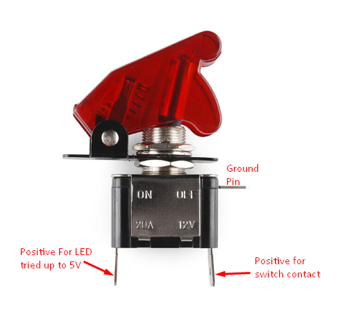
As you can see the ground pin is the contact that is closest to the top of the switch, with the LED and Switch Positive contact as labelled.
Hopefully that helps!
Cheers,
Blayden
Thanks @Blayden that worked great! ![]()
Quick question : How did you figure that out?
Did you use a multi-meter and if so how does that work?
Did you find a datasheet? If so, how did you know what to search?

thx. pix.
1 Like
Hey Pixmusix,
With that switch there were faint markings on the other side of the switch that show a few symbols, I found ground and positive from there and while the LED symbol was faint and unusual, I deduced that was the right pin from knowing the other 2 by process of elimination.
Glad to see you’ve got it up and running and hope it is an awesome addition to your project! I know how satisfying they are from one of my personal Model Rocket Ignition Controller projects!
Cheers,
Blayden
1 Like
I’m sure as I get more experience I’ll be able to figure this kinda stuff on my own too. Until then I appreciate your diagram ![]()
I’d be super interested in seeing or reading about your personal projects.
Is there anything online you can link me too. Do you know of anyone else who has gone down this journey I should check out?
Hey Pixmusix,
I’m not big on making my projects public as of yet, they are mostly stuff for my son at the moment and its not something I am big on putting up on the internet until he gets a bit older and understands digital autonomy a bit better. But hopefully in the coming years I can put some things up to show everyone!
I mainly followed a bunch of guides from other makers similar to this one. But I ended up using an LED push button as my fire button, with a series of a key switch and toggle switch as safeties along the way, with corresponding LEDs to show what was armed. Just a fun little project so that the little one can learn how things work and I don’t have to spend $60+ on a premade one.
Cheers,
Blayden
1 Like
This is the coolest! ![]()
Keeping photos of my daughter off the internet is surprisingly hard. You find yourself checking reflections in photos and asking “do I trust this friend with this photo?” What a world!
Respect and support.
That’s exactly what I’ve been looking for! Thank you Blayden ![]()
2 Likes